
A prefabricated anti-collision wall and its installation method

An anti-collision wall, prefabricated technology, applied in the erection/assembly of bridges, buildings, bridge construction, etc., can solve the problems of unsatisfactory construction quality, damage to the road surface, long time consumption, etc., to shorten the construction period, simplify the installation steps, Assemble the simple effect

Active Publication Date: 2020-10-20
GUANGZHOU UNIVERSITY
View PDF7 Cites 1 Cited by
  • Summary
  • Abstract
  • Description
  • Claims
  • Application Information

AI Technical Summary

Problems solved by technology

The installation process of this traditional anti-collision wall construction method is relatively complicated, and the fine construction is difficult, resulting in unsatisfactory construction quality and difficulty in replacing and dismantling the anti-collision wall
Once a vehicle hits the anti-collision wall and the anti-collision wall cannot continue to realize the corresponding function due to the impact damage, it is easy to cause a secondary accident, so it is necessary to cut the road surface and the bridge deck in time to replace the new anti-collision wall
Since the anti-collision walls in highways and bridges are integrally connected with the road surface and bridges during construction at this stage, if the anti-collision walls are replaced by cutting, the road surface will be damaged or the relative integrity of the bridge deck will be damaged to a certain extent.
At the same time, due to the complex installation and construction process, long time consumption and low efficiency of the anti-collision wall, it is difficult to replace the anti-collision wall.

Method used


Image

  • A prefabricated anti-collision wall and its installation method
  • A prefabricated anti-collision wall and its installation method
  • A prefabricated anti-collision wall and its installation method

Examples


Embodiment Construction

[0033] The present invention will be further described in detail in conjunction with the accompanying drawings and specific embodiments.

[0034] In order to facilitate a unified review of the various reference signs in the drawings of the specification, the unified description of the reference signs appearing in the drawings of the specification is as follows:

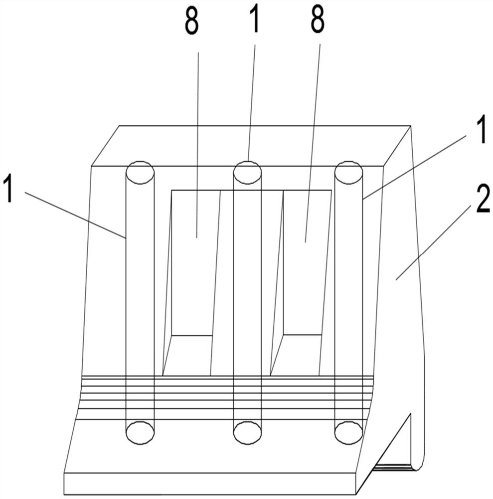
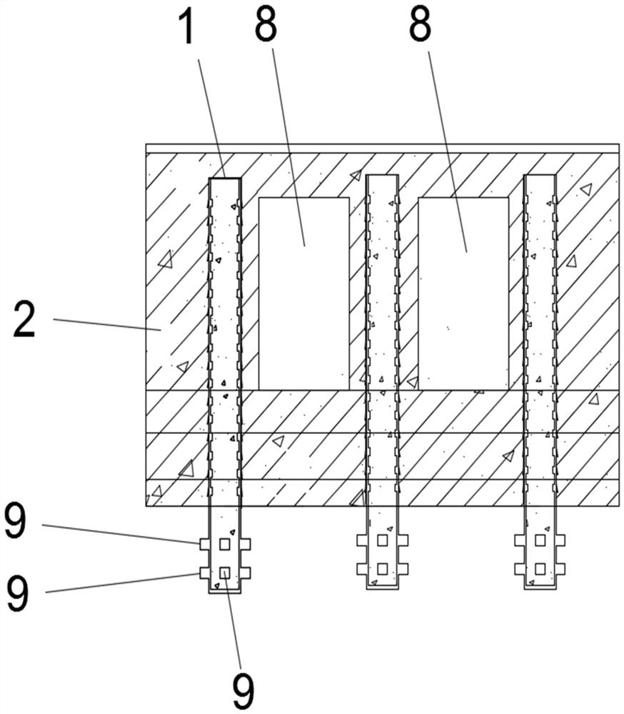
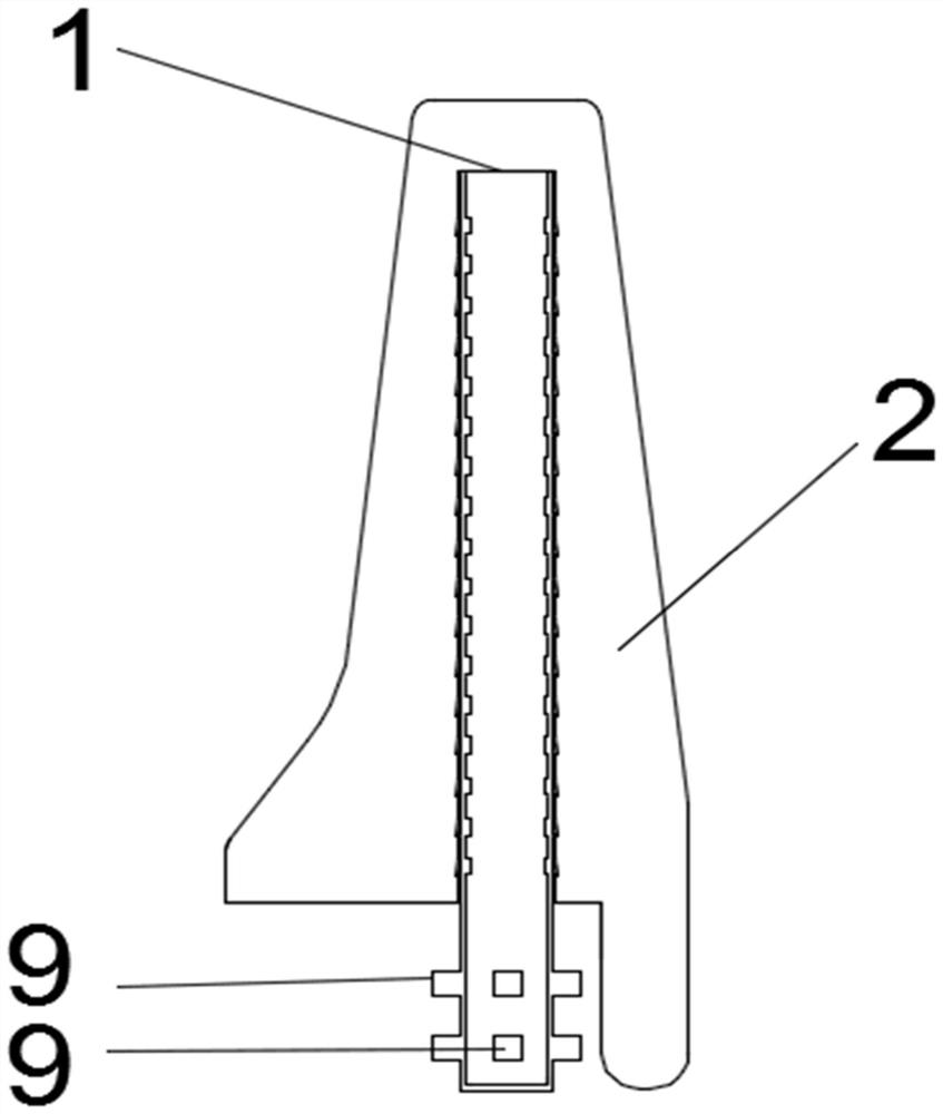
[0035] 1 is the anti-collision tube, 2 is the anti-collision block, 3 is the elastic bump, 4 is the assembly hole, 5 is the assembly slot, 6 is the center through hole, 7 is the fixed bump, 8 is the notch, and 9 is the installation bump , 10 is the installation card position, 11 is the first hole position, 12 is the second hole position, and 13 is the through groove.

[0036] Such as figure 1 , figure 2 , image 3 , Figure 4 , Figure 5 , Image 6 , Figure 7 As shown, an assembled anti-collision wall includes an anti-collision tube installed on the ground and an anti-collision block sleeved on the anti-colli...


PUM


Abstract

The present invention relates to an assembled concrete barrier, comprising anti-crash tubes mounted on the ground and anti-crash blocks sleeved on the anti-crash tubes. An elastic bump is provided on the outer wall of each anti-crash tube; each anti-crash block is provided with assembling holes, and an assembling clamping groove is formed in the inner wall of each assembling hole; the shape of the assembling clamping groove and the shape of the elastic bump are the same; the anti-crash tube penetrates into the assembling hole of the anti-crash block; the elastic bump is embedded into the assembling clamping groove. The present invention further relates to a mounting method for the assembled concrete barrier, comprising the following steps: reserving a mounting clamping position on the ground; enabling a mounting bump on an anti-crash tube to pass through a through groove and then rotating same by a certain angle, so that the mounting bump is clamped in a second hole position; pouring polyurethane elastic concrete, polystyrene foam concrete, or a fiber reinforced composite material into a central through hole of the anti-crash tube; and sleeving an anti-crash block on the anti-crash tube, so that an assembling hole is matched with the anti-crash tube, and an assembling groove is matched with an elastic bump. The present invention relates to the technical field of concrete barriers, and can reduce crash damage to the road surface.

Description

technical field [0001] The invention relates to the technical field of anti-collision walls, in particular to an assembled anti-collision wall and an installation method thereof. Background technique [0002] As an auxiliary structure of the bridge, the anti-collision wall is arranged on the outer edge of the main girder wing plate. It is an important safety protection and has the function of preventing the driving vehicle from driving out of the bridge for some reason. [0003] The current installation and construction process of the anti-collision wall mainly includes: construction preparation, formwork prefabrication splicing number, measuring and setting out, binding steel bars at the same time as measuring and setting out, installing internal formwork at the same time as laying out embedded parts, installing external formwork, concrete pouring, repairing and maintenance. Measurement and positioning, steel bar binding, formwork support, linear adjustment, concrete pouri...

Claims


Application Information

Patent Timeline
Patent Type & Authority Patents(China)
IPC IPC(8): E01D19/00E01D21/00
CPCE01D19/00E01D21/00
Inventor 张力文江祖慊周危章敏邱瑜豪林佳礼麦浩威钟振棠邹志伟刘周强
Owner GUANGZHOU UNIVERSITY
Learn More