Gear grinding machine

A gear grinding machine and machine body technology, which is applied in the field of gear grinding machines, can solve problems such as difficult maintenance, difficult disassembly and assembly, and unreasonable structural design and layout, and achieve the effects of reducing production costs, reasonable weight distribution, and reducing equipment volume

Pending Publication Date: 2019-10-18
HUNAN ZDCY (ZHONGDA CHUANG YUAN) CNC EQUIP CO LTD
View PDF0 Cites 2 Cited by
  • Summary
  • Abstract
  • Description
  • Claims
  • Application Information

AI Technical Summary

Problems solved by technology

In this structure, the guide rails to realize the front and rear sliding of the slide seat are built in the fuselage, which is difficult to disassemble and maintain, and the overall structural design and layout are unreasonable, making it appear top-heavy

Method used


Image

  • Gear grinding machine
  • Gear grinding machine
  • Gear grinding machine

Examples


Embodiment 1

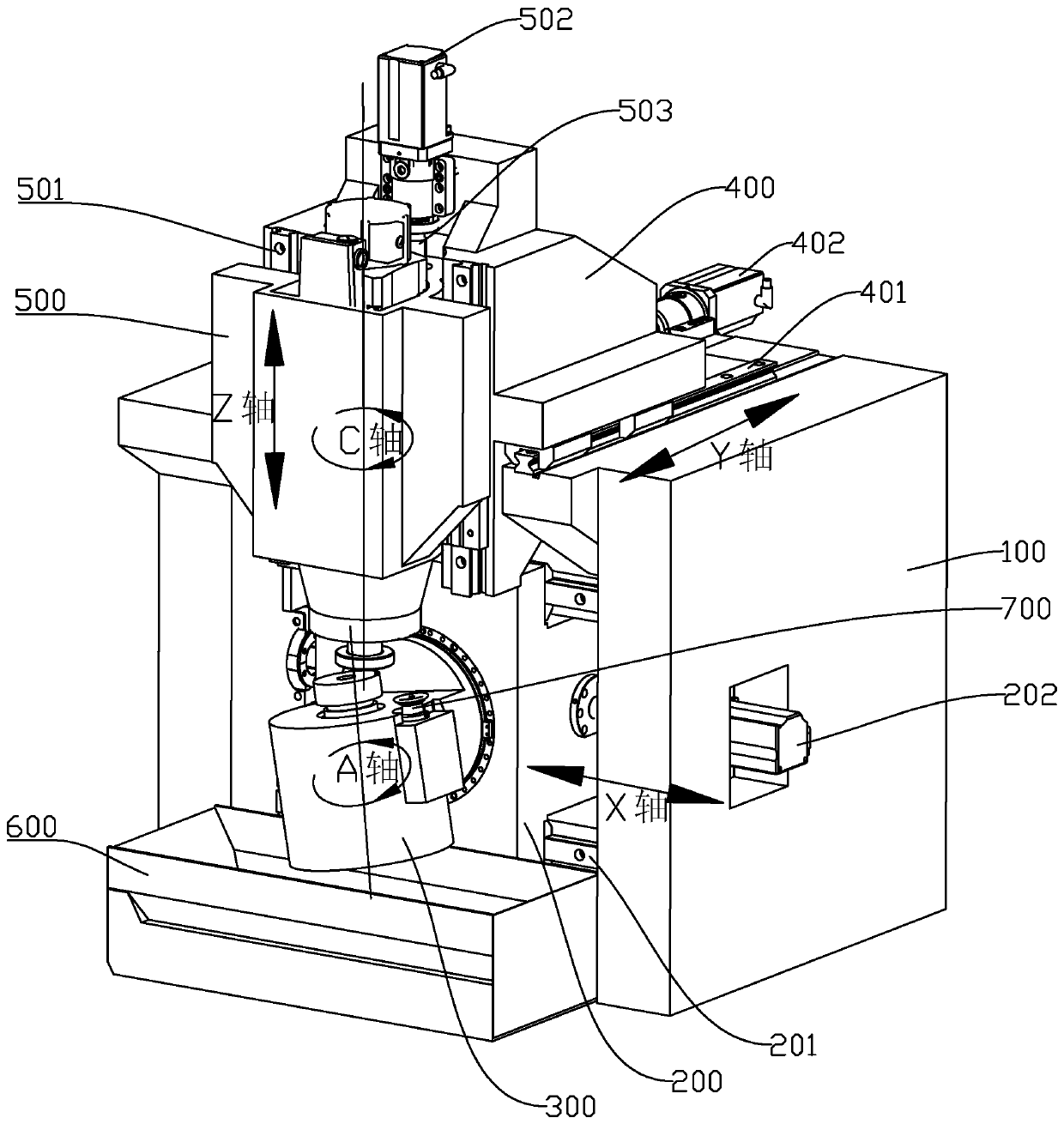
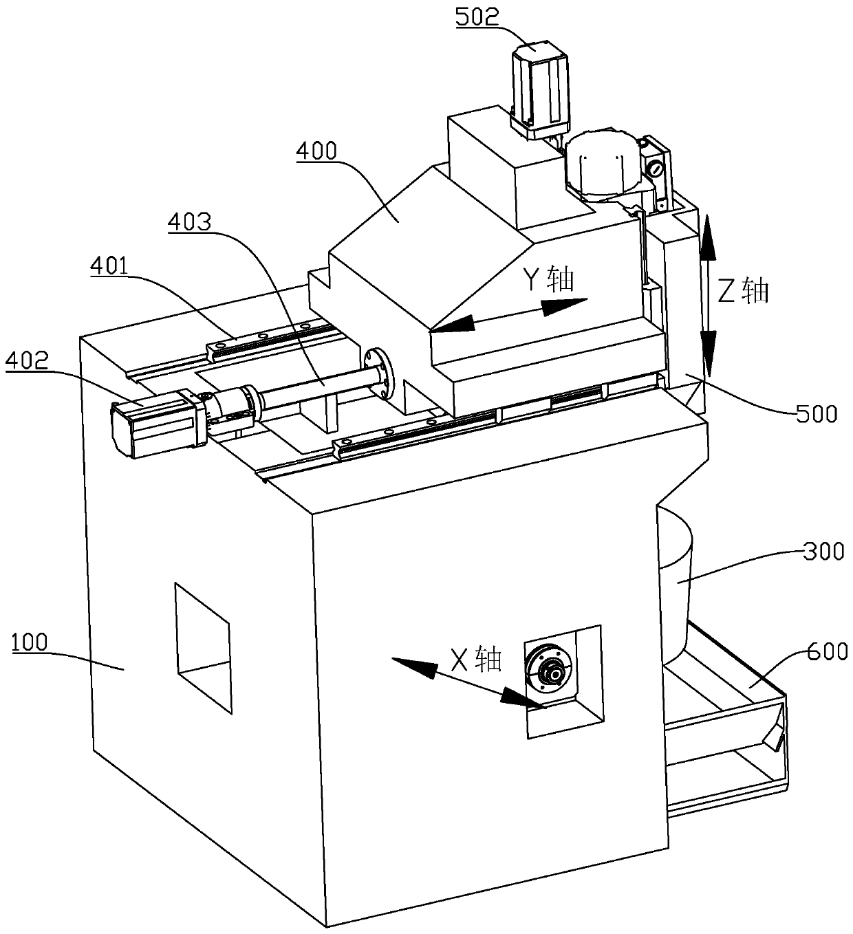
[0030] refer to Figure 1 ~ Figure 3 , the present invention provides a gear grinding machine, comprising:

[0031] A fuselage 100, the side wall of the fuselage 100 is provided with an X-axis guide rail 201 extending along the horizontal axis in the direction of the X-axis;

[0032] The second rotary axis box 200, the second rotary axis box 200 is slidably installed on the X-axis guide rail 201, and the second rotary axis box 200 is provided with a rotary axis B that is horizontal and perpendicular to the X-axis guide rail 201 shaft, the end of the shaft of the rotary shaft B extends outside the second rotary shaft box 200 and is fixedly installed with the first rotary shaft box 300, the first rotary shaft box 300 is provided with a shaft perpendicular to the rotary shaft B the workpiece spindle A axis of the axis, the end of the workpiece spindle A axis is mounted with the workpiece;

[0033] The slide table 400, the slide table 400 is installed on the fuselage 100 so as t...

Embodiment 2

[0050] This embodiment takes Embodiment 1 as the main body, and the difference is that the first drive mechanism, the second drive mechanism and the third drive mechanism in this embodiment are set as linear motors, cylinders or oil cylinders, which directly control the movement of corresponding components, Reduce the setting of the screw rod to achieve the purpose of structural optimization.


PUM


Abstract

The invention discloses a gear grinding machine comprising a machine body, a second rotating shaft box body, a sliding table and a cooling oil tank; the side wall of the machine body is provided withan X-axis guide rail; the second rotating shaft box body is slidably installed on the X-axis guide rail, and internally provided with a rotating shaft B; the tail end of the rotating shaft B is provided with a first rotating shaft box body which is internally provided with a workpiece spindle A, and the end of the workpiece spindle A is provided with a workpiece; the sliding table is movably installed on the machine body, and located above the second rotating shaft box body; the sliding table is provided with a third rotating shaft box body which is internally provided with a grinding wheel spindle C of which the lower end is provided with a grinding wheel; and the cooling oil tank is arranged below the first rotating shaft box body in the X-axis direction. Compared with a traditional structure, the gear grinding machine has the advantages that the three movable shafts are not stacked, and accordingly the removal and installation are simple and convenient; not only can the production efficiency be improved, but also the maintenance is convenient; the weight distribution is more reasonable, and the situation that the gear grinding machine is not top-heavy is avoided, so that the counterweight of the machine body can be further reduced; and the size of the machine is reduced.

Description

technical field [0001] The invention belongs to the technical field of gear processing equipment, and in particular relates to a gear grinding machine. Background technique [0002] In order to process the gear teeth of the spiral bevel gear, the gear grinding machine is equipped with a six-axis transmission mechanism, which specifically includes 3 rotating axes and 3 moving axes. The moving axes include the X, Y, and Z axes that realize the spatial movement adjustment of the grinding wheel and the workpiece. , the rotating shaft includes a workpiece rotating shaft, a grinding wheel rotating shaft and a pendulum shaft for adjusting the angle between the workpiece rotating shaft and the grinding wheel rotating shaft. In addition, the gear grinding machine also includes a grinding wheel dresser, so it is also called a seven-axis structure. [0003] The gear grinding machines currently on the market mainly include a fuselage and a grinding wheel box and a workpiece box located...

Claims


Application Information

Patent Timeline
Patent Type & Authority Applications(China)
IPC IPC(8): B23F1/02B23F15/00B23F23/00
CPCB23F1/02B23F15/00B23F23/00
Inventor 张春晖
Owner HUNAN ZDCY (ZHONGDA CHUANG YUAN) CNC EQUIP CO LTD
Why Eureka
Try Eureka