Eureka AIR delivers breakthrough ideas for toughest innovation challenges, trusted by R&D personnel around the world.

Metal device intelligent quality inspection equipment control system and method based on machine vision and electronic equipment

A metal device and machine vision technology, applied in the field of metal device intelligent quality inspection equipment control system, can solve problems such as insufficient computing power and poor industrial practicability, so as to improve industrial applicability, improve control speed and performance, and reduce problems. effect of probability

Inactive Publication Date: 2019-10-15
创新奇智(广州)科技有限公司
View PDF7 Cites 3 Cited by
  • Summary
  • Abstract
  • Description
  • Claims
  • Application Information

AI Technical Summary

Problems solved by technology

[0003] In order to overcome the shortcomings of insufficient computing power and poor industrial applicability caused by the current intelligent quality inspection equipment control system, the present invention provides a machine vision-based metal device intelligent quality inspection equipment control system, method and electronic equipment

Method used


Image

  • Metal device intelligent quality inspection equipment control system and method based on machine vision and electronic equipment
  • Metal device intelligent quality inspection equipment control system and method based on machine vision and electronic equipment
  • Metal device intelligent quality inspection equipment control system and method based on machine vision and electronic equipment

Examples


Embodiment Construction

[0036] In order to make the purpose, technical solutions and advantages of the present invention more clear, the present invention will be further described in detail below in conjunction with the accompanying drawings and implementation examples. It should be understood that the specific embodiments described here are only used to explain the present invention, not to limit the present invention.

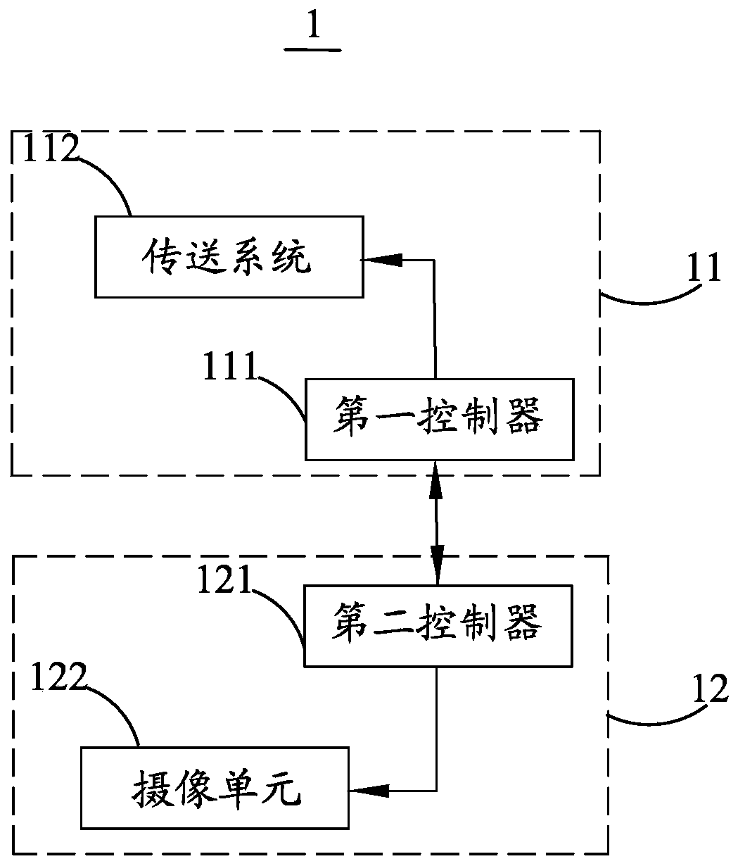
[0037] see figure 1 , the first embodiment of the present invention provides a machine vision-based intelligent quality inspection equipment control system 1 for metal devices, which is used to detect workpieces to be inspected. Optionally, the workpieces to be inspected belong to metal parts on the engine, which is based on The intelligent quality inspection equipment control system 1 of machine vision is set on the assembly line in the engine assembly process.

[0038] The machine vision-based intelligent quality inspection equipment control system 1 for metal devices includes a...


PUM


Abstract

The invention relates to the technical field of engine assembly detection, in particular to a machine vision-based metal device intelligent quality inspection equipment control system, a metal deviceintelligent quality inspection equipment control method and electronic equipment. A to-be-detected workpiece conveying system comprises a first controller and a conveying system. The first controlleris used for controlling the conveying system to convey a to-be-detected workpiece to a designated position. The analysis system comprises a second controller and a camera shooting unit; the first controller sends a signal to the second controller; the second controller drives the camera shooting unit to shoot the to-be-detected workpiece; the second controller analyzes the obtained picture to judge whether the to-be-detected workpiece is an authentic product or an inferior-quality product; a mechanical dynamic to-be-detected workpiece conveying system and a static visual processing system belong to different controllers respectively; the second controller and the first controller are prevented from belonging to the same controller, so that the second controller has enough computing power.The first controller has enough device interfaces, and the complexity of the system is reduced. Meanwhile, the applicability of a quality inspection technology can be well improved.

Description

【Technical field】 [0001] The invention relates to the technical field of engine assembly detection, in particular to a machine vision-based intelligent quality inspection equipment control system for metal devices, a method and electronic equipment. 【Background technique】 [0002] With the rapid development of machine vision inspection technology, it is widely used in many fields. For example, it is applied in the field of quality inspection to inspect parts that need to be assembled to determine whether the parts are qualified. Existing intelligent quality inspection equipment generally includes machine vision systems and mechanical motion control systems, mostly using industrial computers, single-chip microcomputers or PLCs (programmable logic controllers) as the central control system, or equipped with image recognition cards and other peripherals for centralized management of image recognition and defective product handling etc. to control. In the existing technical so...

Claims


Application Information

Patent Timeline
Patent Type & Authority Applications(China)
IPC IPC(8): G06T7/00
CPCG06T7/0004
Inventor 张发恩吴聪颖黄家水唐永亮
Owner 创新奇智(广州)科技有限公司
Why Eureka
Eureka Blog
Learn More