
Urban rail transit bond beam and construction method thereof

A technology of urban rail transit and construction method, which is applied in the field of urban rail transit combined beams and its construction, which can solve the problems of low space utilization, easy cracking of the bottom plate, poor lateral force, etc., and achieve convenient construction and maintenance, and overall weight reduction , Conducive to the effect of rapid construction

Pending Publication Date: 2019-10-15
CHINA MAJOR BRIDGE ENERGINEERING
View PDF0 Cites 1 Cited by
  • Summary
  • Abstract
  • Description
  • Claims
  • Application Information

AI Technical Summary

Problems solved by technology

The common box girder has a large overall height, heavy girder body, low space utilization rate, and heavy overall hoisting
The U-shaped beam solves the above problems to a certain extent, but the U-shaped beam is an open and thin-walled cross-section, the lateral force is poor, and the bottom plate is easy to crack, so it cannot adapt to widening and crossing lines, etc., and the span is limited

Method used


Image

  • Urban rail transit bond beam and construction method thereof
  • Urban rail transit bond beam and construction method thereof
  • Urban rail transit bond beam and construction method thereof

Examples


Embodiment Construction

[0032] The present invention will be described in further detail below in conjunction with the accompanying drawings and embodiments.

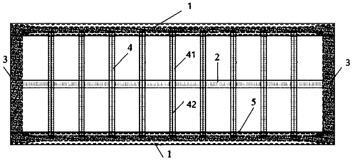
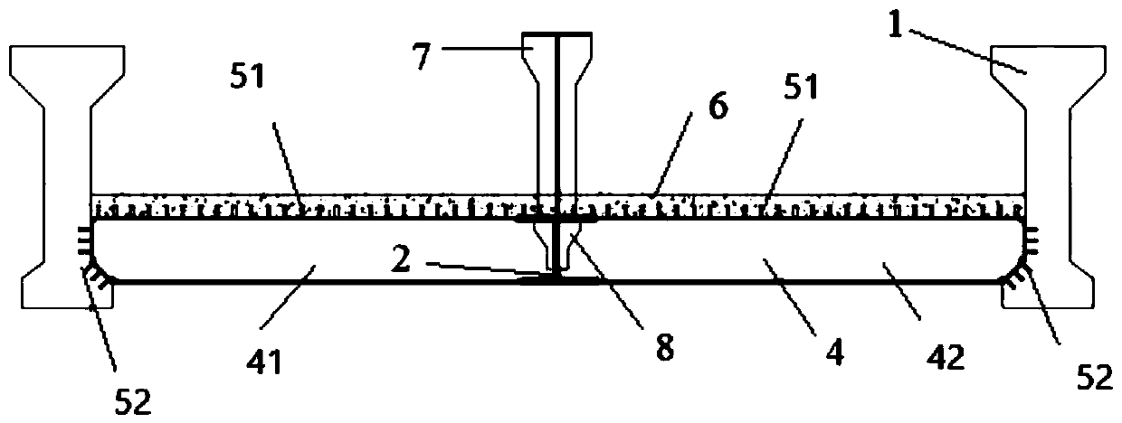
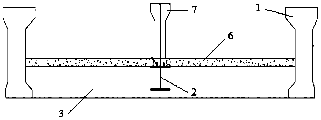
[0033] see Figure 1 to Figure 4 As shown, the embodiment of the present invention provides a kind of urban rail transit combined beam, comprising:

[0034] Two opposite concrete edge stringers 1;

[0035] Two opposite concrete beams 3, the two concrete beams 3 are respectively arranged at the two ends of the two concrete side beams 1, and the two concrete beams 3 and the two concrete side beams 1 form a square Framework;

[0036] A steel longitudinal beam 2, the steel longitudinal beam 2 is arranged in the area between two concrete side longitudinal beams 1, and the two ends of the steel longitudinal beam 2 are respectively connected to the two concrete beams 3;

[0037] Several steel beams 4, each steel beam 4 includes a first beam 41 and a second beam 42, both sides of the first beam 41 and the second beam 42 are respectively connected t...


PUM


Abstract

The invention discloses an urban rail transit bond beam and a construction method thereof and belongs to the technical field of urban rail transit. The urban rail transit bond beam comprises two concrete edge longitudinal beams, two concrete cross beams, a steel longitudinal beam, a plurality of steel cross beams, and a concrete bridge deck slab; the two concrete cross beams are arranged at the two ends of the two concrete edge longitudinal beams respectively, and the two ends of the steel longitudinal beam are connected with the two concrete cross beams respectively; each steel cross beam comprises a first cross beam and a second cross beam, the two sides of the first transverse beam and the two sides of the second transverse beam are respectively connected with the steel longitudinal beam and the concrete edge longitudinal beams, and the first transverse beam, the second transverse beam and the steel longitudinal beam form a supporting surface; and the concrete bridge deck slab is arranged on the supporting surface formed by the first transverse beam, the second transverse beam and the steel longitudinal beam. According to the urban rail transit bond beam provided by the invention, the transverse stress of the beam body is improved, the weight of the beam body component is reduced, and the installation efficiency is improved.

Description

technical field [0001] The invention relates to the technical field of urban rail transit, in particular to an urban rail transit combined beam and a construction method thereof. Background technique [0002] At present, the upper structure of rail transit viaducts generally adopts large box girders, small box girders or U-shaped girders. The common box girder has a large overall height, heavy girder body, low space utilization rate, and heavy lifting overall. The U-shaped beam solves the above problems to a certain extent, but the U-shaped beam is an open thin-walled section, which has poor lateral force and the bottom plate is easy to crack, so it cannot adapt to widening and crossing positions, and its span is limited. Contents of the invention [0003] In view of the above-mentioned defects in the prior art, the present invention provides an urban rail transit combined beam to improve the lateral force on the beam body, reduce the weight of the beam body components, a...

Claims


Application Information

Patent Timeline
Patent Type & Authority Applications(China)
IPC IPC(8): E01D2/00E01D21/00
CPCE01D2/00E01D21/00E01D2101/268
Inventor 张强梅江兵曹春明曹红林顾颖罗祎谢凯悦李苏
Owner CHINA MAJOR BRIDGE ENERGINEERING
Learn More