an electronic device

An electronic equipment and electronic technology, which is applied to the structural parts of electrical equipment, electrical components, magnetic field/electric field shielding, etc., can solve the problems of ultra-thin design of terminal equipment, long transmission path to the middle frame, insufficient heat dissipation capacity of the chip, etc. problem, to achieve the effect of improving the consistency of the screen effect, improving the screen effect, and facilitating the ultra-thin design

Active Publication Date: 2020-12-04
HUAWEI TECH CO LTD
View PDF16 Cites 0 Cited by
  • Summary
  • Abstract
  • Description
  • Claims
  • Application Information

AI Technical Summary

Problems solved by technology

[0005] In general, the thickness of each layer of thermal gel is usually about 0.1 mm, and the thickness of the shield is also 0.1-0.15 mm, which makes the heat transfer path from the chip to the middle frame longer, and the heat transfer resistance is too large , the heat dissipation capability of the chip is insufficient
In addition, this structure is not conducive to the ultra-thin design of terminal equipment

Method used


Image

  • an electronic device
  • an electronic device
  • an electronic device

Examples


Embodiment Construction

[0041] Embodiments of the present application are described in detail below, examples of which are shown in the drawings, wherein the same or similar reference numerals denote the same or similar elements or elements having the same or similar functions throughout. The embodiments described below by referring to the figures are exemplary, are only for explaining the present application, and should not be construed as limiting the present application.

[0042]In the description of the present application, it should be understood that the terms "first" and "second" are used for description purposes only, and cannot be interpreted as indicating or implying relative importance or implicitly indicating the quantity of indicated technical features. Thus, a feature defined as "first" or "second" may explicitly or implicitly include one or more of said features. In the description of the present application, "plurality" means two or more, unless otherwise specifically defined.

[004...


PUM


Abstract

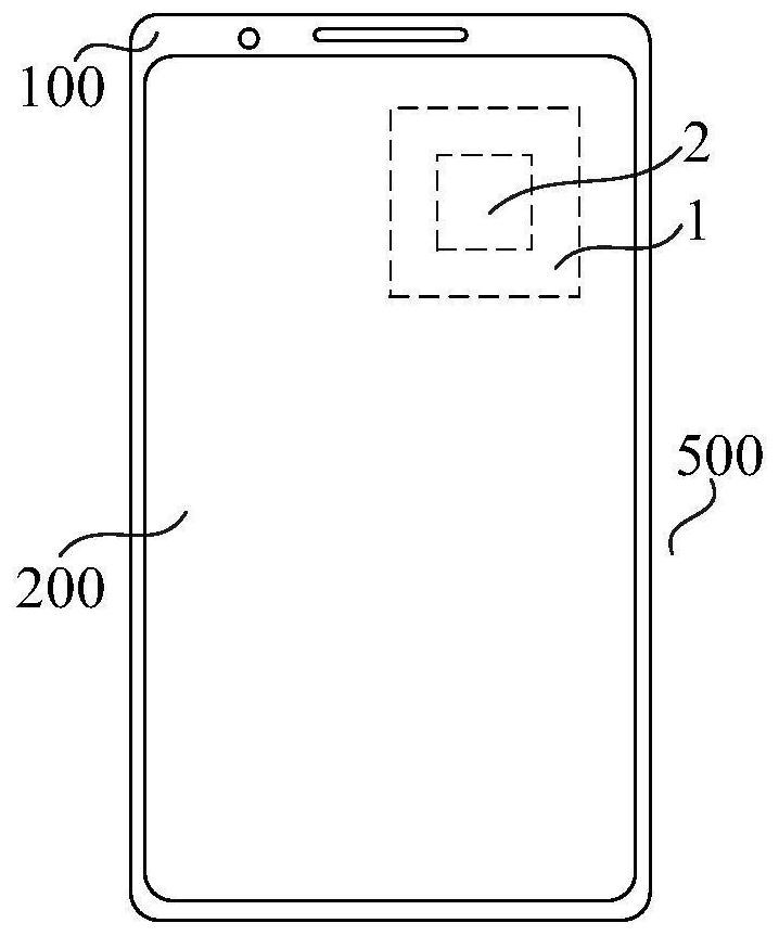
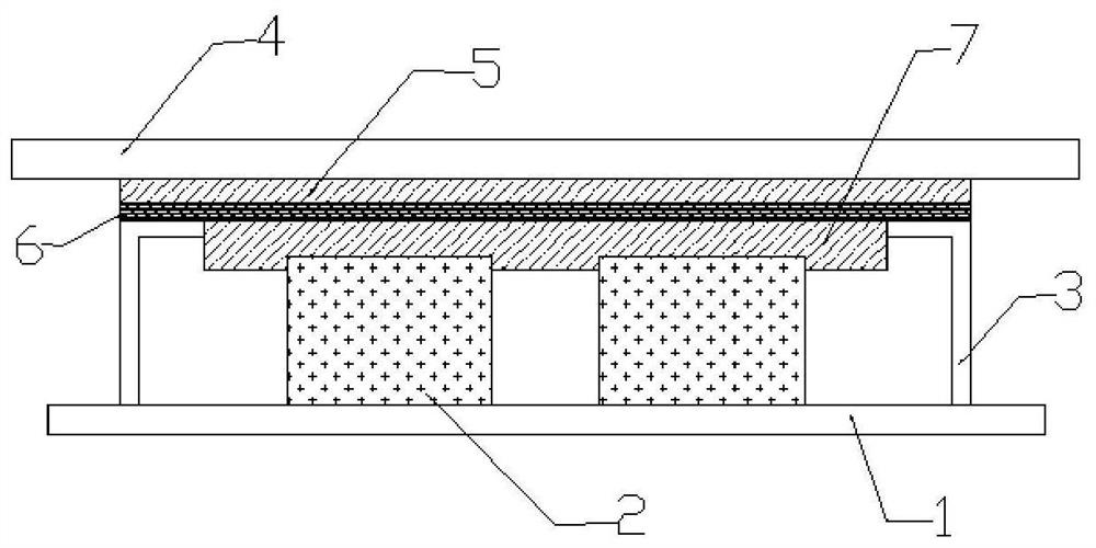
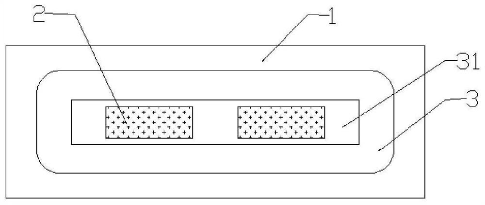
The present application provides an electronic device, comprising: a circuit board, on which an electronic heating element is arranged; a shielding frame, which is mounted on the circuit board and surrounds a sidewall surface of the electronic heating element, and an opening is formed in the shielding frame; a heat dissipation member, which is arranged above the opening, the heat dissipation member is connected to the electronic heating element sequentially through a first elastic heat conducting layer, a first ultra-thin conductive layer and a second elastic heat conducting layer, and the first elastic heat conducting layer and the second elastic heat conducting layer are in a compressed state; the area of the first ultra-thin conductive layer is greater than or equal to the area of the opening, the first ultra-thin conductive layer is electrically connected with the shielding frame, and the shielding frame, the first ultra-thin conductive layer and the circuit board form an electromagnetic shielding cavity for accommodating the electronic heating element. The electronic device of the present application can enhance the heat dissipation capability of the electronic heating element while ensuring the shielding effect on the electronic heating element.

Description

technical field [0001] The present application relates to the technical field of chip heat dissipation, and in particular to an electronic device. Background technique [0002] With the advancement of science and technology and the change of people's communication methods, terminal equipment is more and more favored by consumers due to its dominant position. At the same time, people have higher and higher requirements for terminal equipment, such as high performance, high reliability, super Thinning etc. [0003] There are many high power consumption chips in the terminal equipment, such as application processor (application processor, AP), radio frequency amplifier, etc. These high power consumption chips are not only a high heat source, but also a source of electromagnetic interference (EMI). EMI shielding is a key factor that affects the performance of various modules such as antennas in terminal equipment. At the same time, the quality of heat dissipation also determine...

Claims


Application Information

Patent Timeline
Patent Type & Authority Patents(China)
IPC IPC(8): H05K7/20H05K9/00
CPCH05K7/20472H05K9/0022
Inventor 杜白虞学犬李得亮
Owner HUAWEI TECH CO LTD
Why Eureka
Try Eureka