
Gas heat pump device based on heat source tower

A technology of gas heat pump and heat source tower, which is applied to machines using waste heat, heating methods, household heating, etc. It can solve problems such as inability to obtain air heat, waste of resources, and increased initial investment in equipment, so as to improve the utilization factor of primary energy, Avoid the problem of frosting and solve the effect of excess heat

Active Publication Date: 2019-10-11
UNIV OF SHANGHAI FOR SCI & TECH
View PDF20 Cites 10 Cited by
  • Summary
  • Abstract
  • Description
  • Claims
  • Application Information

AI Technical Summary

Problems solved by technology

[0003] Chinese patent CN101634501A discloses a frost-free air source heat pump system. The frost-free air source heat pump system can realize the function of a water-cooled chiller in summer; in winter, it obtains low-level heat from the air through the solution circulation process in the cooling tower and heats it through the heat pump. However, the system is too complicated when the solution is regenerated, too much equipment increases the initial investment, and the equipment is idle in summer, resulting in a great waste of resources
The system has issues with the unit being idle in summer while not being able to capture the heat from the air in winter defrost mode

Method used


Image

  • Gas heat pump device based on heat source tower

Examples


Embodiment Construction

[0019] Structure, principle and mode of operation of the present invention are further elaborated below in conjunction with accompanying drawing:

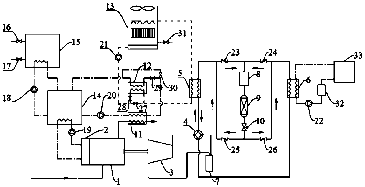
[0020] Such as figure 1 As shown, a gas heat pump device based on a heat source tower mainly includes a solution circulation unit, a gas heat pump unit, a waste heat recovery unit and a user unit.

[0021] The gas heat pump unit includes gas engine 1, compressor 3, four-way reversing valve 4, solution-refrigerant heat exchanger 5, water-refrigerant heat exchanger 6, liquid receiver 8, dry filter 9, electronic expansion valve 10. Gas-liquid separator 7, first check valve 23, second check valve 24, third check valve 25 and fourth check valve 26, wherein the gas engine 1 and compressor 3 are connected through a coupling , the compressor 3 is connected to the gas-liquid separator 7 through the four-way reversing valve 4 to form a circuit, and the four-way reversing valve 4 is connected to the solution-refrigerant heat exchanger 5, the...


PUM


Abstract

The invention relates to a gas heat pump device based on a heat source tower. The gas heat pump device comprises a solution circulation unit, a gas heat pump unit and a waste heat recycling unit, a solution outlet of the heat source tower in the solution circulation unit is connected with a solution inlet of a solution-refrigerant heat exchanger through a solution pump and a first solution valve,a solution outlet of the solution-refrigerant heat exchanger is connected with a solution inlet of the heat source tower, a cooling water circulating water tank, a cylinder sleeve water circulating water pump and a cylinder sleeve heat exchanger in the waste heat recycling unit are connected through a pipeline to form a cylinder sleeve water waste heat recovery loop, the cooling water circulatingwater tank, a second water pump, a flue gas heat exchanger, a first water valve and the cooling water circulating water tank are sequentially connected through a pipeline to form a flue gas waste heatrecovery loop, and a waste heat utilization loop is formed by sequentially connecting the cooling water circulating water tank, the second water pump, the flue gas heat exchanger, a second water valve, a regeneration heater and the cooling water circulating water tank through a pipeline and sequentially connecting the cooling water circulating water tank, the first water pump, a domestic hot water tank and the cooling water circulating water tank through a pipeline.

Description

technical field [0001] The invention relates to a gas heat pump system, in particular to a gas heat pump device based on a heat source tower. Background technique [0002] The gas heat pump system is a heat pump system driven by an engine and fueled by natural gas. With the increase of the proportion of natural gas energy utilization and the enhancement of energy conservation and environmental protection awareness, the gas heat pump technology continues to develop. The air source gas heat pump system often has the problem of frosting on the evaporator in winter, which increases the thermal resistance and wind resistance, which will directly affect the heat exchange efficiency of the evaporator, thereby affecting the operation of the whole machine. It can be seen that defrosting is adopted for the gas heat pump system. Or anti-frost measures are necessary. Existing defrosting or anti-frost technologies mostly use the waste heat of the gas heat pump system to remove frost or ...

Claims


Application Information

Patent Timeline
Patent Type & Authority Applications(China)
IPC IPC(8): F25B13/00F25B27/02F25B49/02F24D3/08F24D3/18F24F5/00
CPCF24D3/082F24D3/18F24F5/001F25B13/00F25B27/02F25B49/02Y02B30/52Y02A30/274
Inventor 张鑫张柯杨文娟张华
Owner UNIV OF SHANGHAI FOR SCI & TECH
Learn More