An automatic side clamping device for sawing steel sheet piles
A technology of clamping device and steel sheet pile, which is applied in the direction of positioning device, clamping, manufacturing tools, etc., can solve the problems of uneven wear and movement of saw blades, and affect the production rhythm of rolling line, etc., and achieve the effect of convenient maintenance and repair
- Summary
- Abstract
- Description
- Claims
- Application Information
AI Technical Summary
Problems solved by technology
Method used
Image

Examples
Embodiment 1
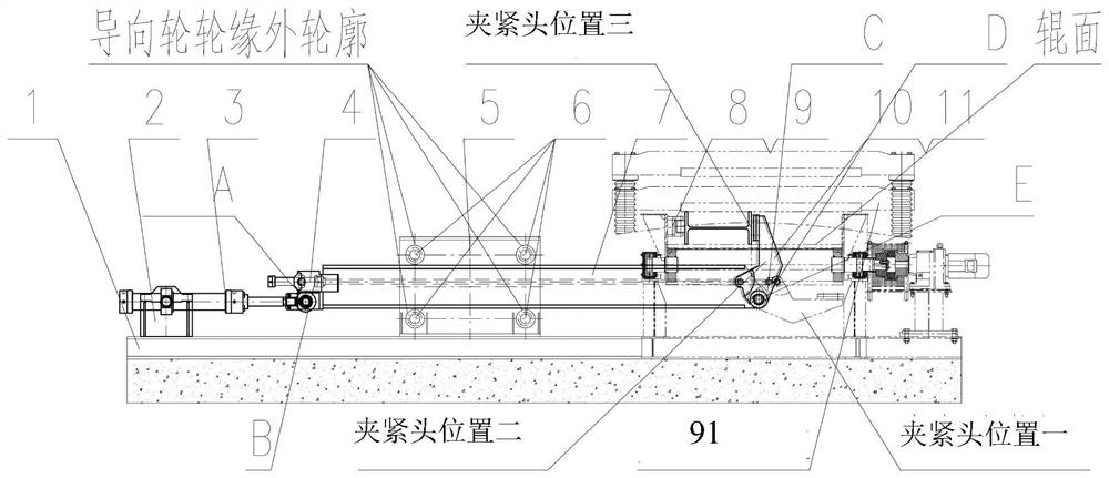
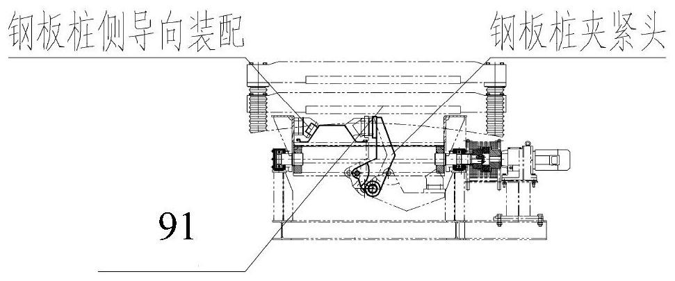
[0023] like figure 1 FIG -3 A steel sheet pile (H-beam) according to the present embodiment of the automatic cutting side of the clamping device, comprising a drive system, a clamping system, a support guide system, the side guide roller assembly.
[0024] The drive system along the side two gripping means are arranged symmetrically about a centerline, each structure exactly the same drive system, the drive system to be located above the clamping apparatus connection relationship of the center line, the drive system comprises a base 1, a hydraulic cylinder mount 2, a first intermediate shaft swing cylinder 3, a first intermediate shaft swing the swing shaft 3 of the hydraulic cylinder is articulated on the support cylinder 2, a first intermediate cylinder axis of oscillation of the flat head 3 is hinged clamping system the clamping frame 7 is fixed to the left ear seat A, a first intermediate shaft swing cylinder 3 tail built-pressure detection sensor, the cylinder holder 2 is fix...
Embodiment 2
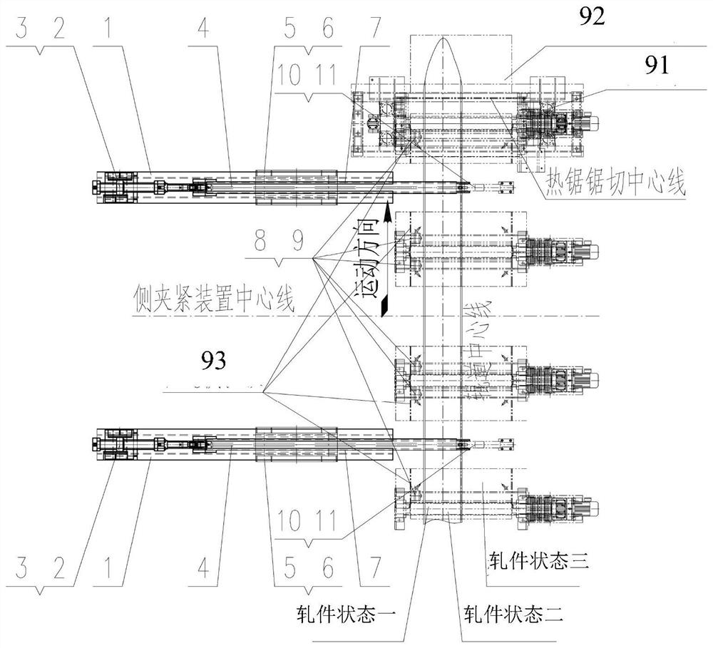
[0028] On the basis of the above-described embodiment, the side guide roller assembly 9 is mounted on the left side of the centerline of the roller track 93 of the side dams, a plurality of sets are arranged in the movement direction, the support bracket comprises a guide system 8, the guide rollers 9 , the holder 8 fixed to the side flap, the guide roller 9 is hinged on the bracket 8, the guide rollers 9 in the center of the bracket about the hinge 8 is free to rotate.
[0029]Clamping entire side process is as follows: the first step so that the second swing shaft intermediate the two hydraulic cylinder piston rod 4 is fully extended, the two clamping heads 10 is located below the horizontal surface of the roll, while the first two the intermediate shaft of the hydraulic swing cylinder rod 3 is fully extended, the position of the two clamping heads 10 is to the right of the center line of the roller, i.e. the position of a gripping head 10; the second step is completed blooming ...
Embodiment 3
[0031] In the embodiments based on the above embodiment, the tilting also increased the removing means 92, comprising a tipping frame, wear plates, the support base, the support cylinder, the intermediate cylinder axis of oscillation.
[0032] The seat support pivot axis intermediate along the cylinder centerline symmetrically arranged above the fixed support base (left side of the centerline of the roller) at a side of the roller frame 97.
[0033] Said tilting frame along a pivot axis intermediate cylinder disposed symmetrically about a centerline, wear plates secured to the tipping frame, the frame A lug plate 2 is hinged to the side of the tilting pivot axis located in the middle of the left cylinder is fixed to the roll center line supporting mount 97 on the frame 121, the tilting frame hinged lug plate 122 to the B side of the rocking shaft in the middle of the right side of the center line of the hydraulic cylinder 121 fixed to the supporting mount 97 on the roller stand.
...
PUM
 Abstract
Description
Claims
Application Information
 - R&D
- Intellectual Property
- Life Sciences
- Materials
- Tech Scout
- Unparalleled Data Quality
- Higher Quality Content
- 60% Fewer Hallucinations
Browse by: Latest US Patents, China's latest patents, Technical Efficacy Thesaurus, Application Domain, Technology Topic, Popular Technical Reports.
© 2025 PatSnap. All rights reserved.Legal|Privacy policy|Modern Slavery Act Transparency Statement|Sitemap|About US| Contact US: help@patsnap.com