
Spinning machine optimal balance structure and method thereof

A technology of balanced structure and laying head, which is applied to bending workpieces, metal processing equipment, metal rolling, etc., can solve problems such as difficulty in balancing the laying head, and achieve the effect of convenient operation and favorable processing

Pending Publication Date: 2019-10-08
CISDI RES & DEV CO LTD
View PDF0 Cites 3 Cited by
  • Summary
  • Abstract
  • Description
  • Claims
  • Application Information

AI Technical Summary

Problems solved by technology

[0004] The purpose of the present invention is to provide an optimized balance structure of a laying machine, which can realize rapid balance, so as to solve the difficult situation of balancing the laying machine on the industrial site

Method used


Image

  • Spinning machine optimal balance structure and method thereof

Examples


Embodiment Construction

[0019] Embodiments of the present invention are described below through specific examples, and those skilled in the art can easily understand other advantages and effects of the present invention from the content disclosed in this specification. The present invention can also be implemented or applied through other different specific implementation modes, and various modifications or changes can be made to the details in this specification based on different viewpoints and applications without departing from the spirit of the present invention. It should be noted that the diagrams provided in the following embodiments are only schematically illustrating the basic concept of the present invention, and the following embodiments and the features in the embodiments can be combined with each other in the case of no conflict.

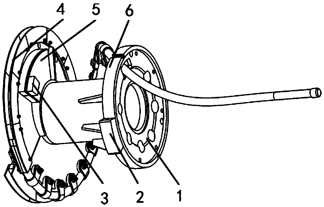
[0020] refer to figure 1 , an optimized balance structure of a laying head in this embodiment, the laying head includes a laying head 1 and a guide groove 4 ...


PUM


Abstract

The invention discloses a spinning machine optimal balance structure and a method thereof, and belongs to the technical field of metallurgy equipment. A spinning machine comprises a spinning head anda guide slot formed in the spinning head; an optimal balance structure comprises a boss, a first balancing weight block and a second balancing weight block; the boss is arranged on a spiral surface ofthe guide slot; the deviation surface deviated from one side of spinning of the guide slot is used as a first balancing weight surface; the first balancing weight block is arranged on the first balancing weight surface; and the second balancing weight block is arranged on a second balancing weight surface, far away from the circumferential direction of one end of the guide slot, selected on the spinning head. According to the optimal balance structure provided by the invention, fast balancing can be realized, and the problem of difficulty in balancing a spinning machine in an industrial siteis solved. By adopting the optimal balance structure, during the balancing of a rotor of the spinning machine, fast balancing can be realized only through adding a balancing weight with small mass ona designed special balancing surface, and the spinning machine optimal balance structure is convenient to operate and beneficial to processing.

Description

technical field [0001] The invention belongs to the technical field of metallurgical equipment, and relates to an optimized balance structure of a laying machine and a method thereof. Background technique [0002] The wire laying machine is one of the core equipment in the high-speed wire rod production line unit. Its function is to bend the continuous straight rolling material passing through it into a circular rolling material ring for transportation and use. The rotating part of the laying machine is mainly composed of a rotor, a spinning head and a rotating tube. The rotating tube is installed in the rotor. The spinning head is fixed on the rotor with a cantilever structure. The motor drives the rotor through a pair of bevel gears. rotate around its axis. The rotating speed of the laying head rotor can reach about 2200r / min, and the rotating diameter is large. Running at such a high speed requires the laying head to have high balance accuracy and reduce the vibration o...

Claims


Application Information

Patent Timeline
Patent Type & Authority Applications(China)
IPC IPC(8): B21B41/00
CPCB21B41/00
Inventor 穆杨陈莹卷王式研
Owner CISDI RES & DEV CO LTD
Learn More