
Construction Method of Prestressed Tendons in Continuous Rigid Frame Bridges

A technology of prestressed tendons and construction methods, which is applied to bridges, bridge construction, bridge materials, etc., can solve the problems of high resistance at the head of steel beams and insufficient smoothness of beam penetration, and achieve smooth beam penetration, reduced resistance, and smooth penetration of steel beams. beam smooth effect

Active Publication Date: 2020-11-17
中建四局贵州投资建设有限公司
View PDF8 Cites 0 Cited by
  • Summary
  • Abstract
  • Description
  • Claims
  • Application Information

AI Technical Summary

Problems solved by technology

[0006] The purpose of the present invention is to provide a construction method for prestressed tendons of continuous rigid-frame bridges, so as to solve the problem that the existing prestressed steel beams are not smooth enough due to the large resistance at the head of the steel beams when passing through the beams

Method used


Image

  • Construction Method of Prestressed Tendons in Continuous Rigid Frame Bridges
  • Construction Method of Prestressed Tendons in Continuous Rigid Frame Bridges
  • Construction Method of Prestressed Tendons in Continuous Rigid Frame Bridges

Examples


Embodiment 1

[0036] This embodiment is applicable to the steel bundle length within 50m.

[0037] The continuous rigid frame bridge prestressed tendon construction method of the present embodiment comprises the following steps:

[0038] Step A. Preparation before wearing:

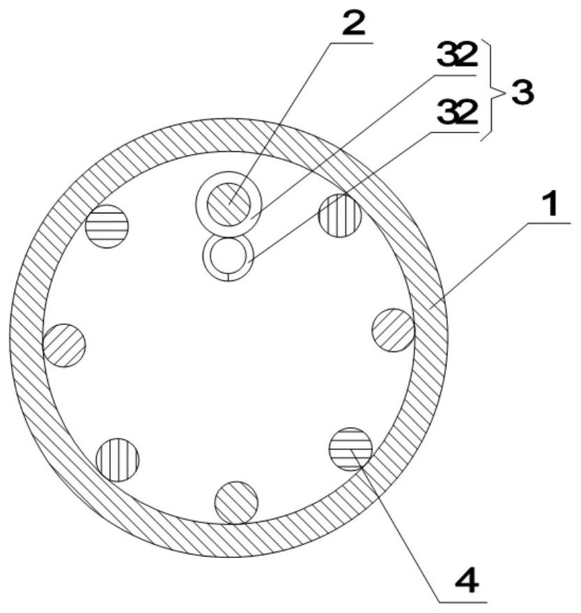
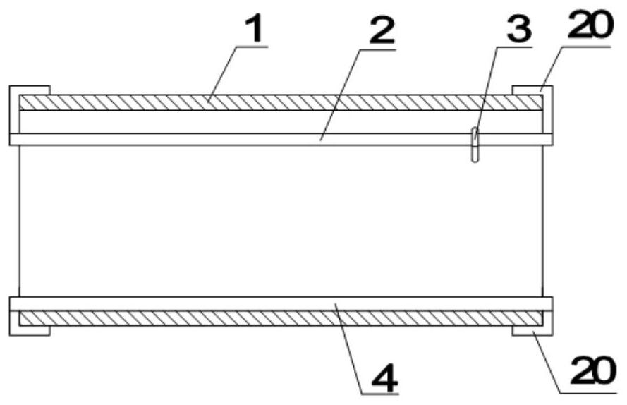
[0039] like figure 1 and figure 2 As shown, first prepare a guide rib 2, a plurality of reinforcing ribs 4 and a buckle 3, and the number of reinforcing ribs 4 in this embodiment is seven. The structure of buckle 3 is as figure 1 As shown, it includes a sliding ring 31 at the top and a guide ring 32 at the bottom. The bottom of the guide ring 32 has an opening that can be closed. An anti-slip layer made of elastic rubber is fixed on the inside.

[0040] Insert the sliding ring 31 of the buckle 3 into the guide rib 2 first, then insert the guide rib 2 and the reinforcing rib 4 into the prestressed bellows 1, and expose the two ends of the guiding rib 2 and the reinforcing rib 4 to the prestressed bellows 1 The par...

Embodiment 2

[0052] The difference between this embodiment and Embodiment 1 is that this embodiment does not use manual beam threading, but uses a 5T winch threading machine. This embodiment is suitable for steel beams with a length of more than 50 m.

Embodiment 3

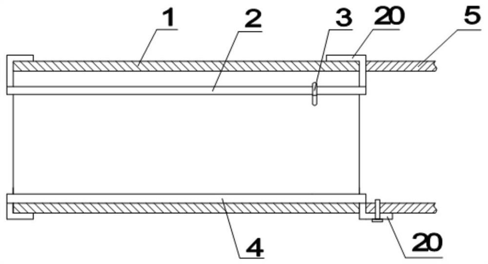
[0054] The difference between this embodiment and embodiment one and embodiment two is: the installation of the anchor end 5 of the steel beam is also included between step B and step C, combined image 3 As shown, when installing, first align the anchor end 5 with the end of the prestressed corrugated pipe 1, and then use a wrench to fasten the fasteners 2 at the ends of each reinforcing rib 4 on the anchor end 5, and then fasten the fasteners 2 with fastening bolts. Being fixed together with the anchor end 5 can strengthen the connection strength between the prestressed bellows 1 and the anchor end 5 .


PUM


Abstract

The invention belongs to the technical field of bridge construction, and particularly discloses a construction method of prestressed tendons of a continuous rigid frame bridge. The construction methodcomprises the following steps that A, prepares are made before beam penetrating; B, bidirectional prestressed beam penetrating is carried out, wherein beam penetrating is carried out from the two sides of a prestressed corrugated pipe, during beam penetrating, a snap ring is firstly located at the end of the prestressed corrugated pipe, the head of a steel beam penetrates into the snap ring, thesnap ring is tightly buckled, then the steel beam gradually penetrates into the prestressed corrugated pipe, the snap ring is driven to move to the other end of the prestressed corrugated pipe in thesteel beam motion process, after beam penetrating of the single steel beam is finished, the snap ring is loosened, steel bars in the snap ring fall to the inner bottom of the prestressed corrugated pipe, then the steel beam is cut off, single steel beam penetrating is carried out from the other end of the prestressed corrugated pipe according to the above method, and operation is circulated in this way till beam penetrating is finished; C, the prestressed tendons are stretched; and D, pipeline mud jacking is carried out.

Description

technical field [0001] The invention relates to the technical field of bridge construction, in particular to a construction method for prestressed tendons of continuous rigid frame bridges. Background technique [0002] Continuous rigid frame bridge is a commonly used structural system in the construction of long-span bridges. - Rigid frame bridges are all prestressed concrete structures. [0003] The prestressing technology adopted by the bridge is to add tension in the components in advance, so that the prestressed tensioned components bear the tensile stress, and then make it produce a certain deformation to cope with the load on the structure itself, including the load of the component's own weight, Wind loads, snow loads, earthquake loads, etc. [0004] The existing prestressed tension usually adopts the post-tensioning method. The post-tensioning method is to pour concrete first and reserve the position of the prestressed tendon channel. After the concrete strength r...

Claims


Application Information

Patent Timeline
Patent Type & Authority Patents(China)
IPC IPC(8): E01D21/00E04G21/12E01D101/28
CPCE01D21/00E01D2101/28E04G21/12
Inventor 时小兵漆久亮王军罗峙
Owner 中建四局贵州投资建设有限公司
Learn More