
A new type of uncoiler

An uncoiler, a new type of technology, applied in the field of metallurgy, can solve the problem that the switcher cannot realize the lower uncoil, and achieve the effect of light weight, easy maintenance and simple structure

Active Publication Date: 2015-12-02
WISDRI ENG & RES INC LTD
View PDF7 Cites 0 Cited by
  • Summary
  • Abstract
  • Description
  • Claims
  • Application Information

AI Technical Summary

Problems solved by technology

[0003] In view of the above problems, the purpose of the present invention is to provide a type of uncoiler, aiming to solve the technical problem that the existing switchgear cannot realize the lower uncoiling, and cannot be applied to uncoiling of strip steel with relatively thin thickness or relatively soft hardness.

Method used


Image

  • A new type of uncoiler
  • A new type of uncoiler
  • A new type of uncoiler

Examples


Embodiment Construction

[0013] In order to make the object, technical solution and advantages of the present invention clearer, the present invention will be further described in detail below in conjunction with the accompanying drawings and embodiments. It should be understood that the specific embodiments described here are only used to explain the present invention, not to limit the present invention.

[0014] In order to illustrate the technical solutions of the present invention, specific examples are used below to illustrate.

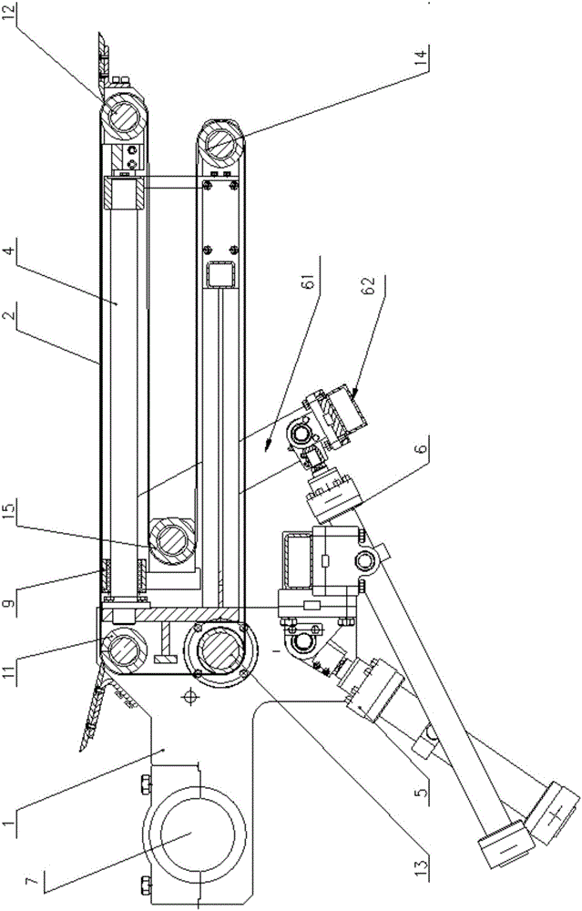
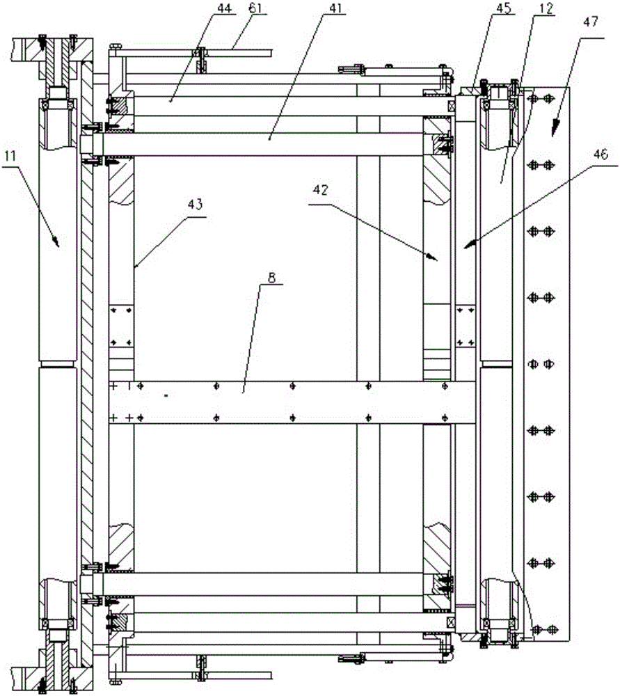
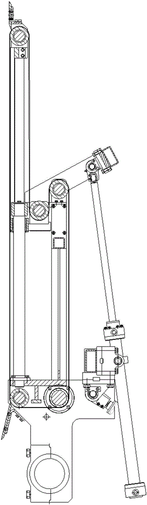
[0015] figure 1 and image 3 The front view structures of the two working states of the new uncoiler provided by the embodiment of the present invention are respectively shown, figure 2 and Figure 4 The top view structure and partial right view structure of the new uncoiler are respectively shown, and only the parts related to the embodiment of the present invention are shown for convenience of description.

[0016] refer to Figure 1-Figure 4 The information unco...


PUM


Abstract

The invention belongs to the field of metallurgy and provides a novel uncoiling machine. The novel uncoiling machine comprises a rack and five steel rollers installed on the rack. The five steel rollers are tightly sleeved with an annular conveying belt, and the rack is further provided with a driving device used for driving one steel roller to rotate. The uncoiling machine further comprises a sliding mechanism, a swing hydraulic cylinder and a telescopic hydraulic cylinder. The rack is provided with a rotary shaft, the head of the swing hydraulic cylinder is fixed to the rack, and a cylinder body is located on next equipment. A telescopic hydraulic cylinder body is fixed to the rack, the head of the telescopic hydraulic cylinder drives the sliding mechanism to make the steel roller located at the far end slide front and back, and the sliding mechanism is further provided with a magnet. Through arranging the swing hydraulic cylinder which drives the uncoiling machine to swing in the vertical direction and the telescopic hydraulic cylinder which drives the uncoiling machines to retract and stretch in the horizontal direction, upper uncoiling and lower uncoiling of the uncoiling machine are achieved, and the uncoiling machine is particularly suitable for band steel which is small in thickness (smaller than 0.2 mm) or low in rigidity.

Description

technical field [0001] The invention belongs to the technical field of metallurgy, and in particular relates to a novel uncoiler. Background technique [0002] The uncoiler is generally located between the uncoiler and the next equipment (such as the steering pinch roller). In the strip steel production line in the metallurgical industry, according to production needs, its function is to guide the strip head of the steel coil to the strip-threading position and turn the strip head of the steel coil Bring in the next device. However, the current uncoiler generally can only achieve upper uncoiling, but when the strip steel thickness is relatively thin (less than 0.2mm) or the hardness is relatively soft in the upper uncoiling condition, the strip threading process is often not smooth. During the threading process of steel crawling upwards, the belt head is often stuck somewhere in the guide plate of the uncoiler and stagnates, which affects the production rhythm and reduces p...

Claims


Application Information

Patent Timeline
Patent Type & Authority Patents(China)
IPC IPC(8): B21C47/26
Inventor 杨帆谢少东梁芳张齐兵
Owner WISDRI ENG & RES INC LTD
Learn More