Wireless electric energy transmission system based on three resonance coils and transmission method of wireless electric energy transmission system
A wireless power transmission and resonant coil technology, applied in circuit devices, electrical components, etc., can solve the problems of circuit occupying space and increasing power loss, and achieve the effects of small standby power loss, reduced energy radiation, and strong robustness.
- Summary
- Abstract
- Description
- Claims
- Application Information
AI Technical Summary
Problems solved by technology
Method used
Image


Examples
Embodiment 1
[0061] Embodiment 1: A second-order PT symmetrical wireless power transmission system and operation method based on two resonant coils
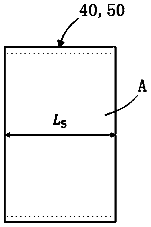
[0062] Such as Figure 1 to Figure 6 As shown, the system of Embodiment 1 includes a Keysight E5071C network analyzer 10 , a non-resonant source coil 20 , two resonant coils (transmitting coil 40 and receiving coil 50 ) with the same resonant frequency, and a non-resonant load coil 30 . The non-resonant coil is composed of a transparent cylindrical plexiglass tube A and a litz wire B, and the resonant coil is composed of a transparent cylindrical plexiglass tube A, a litz wire B and a capacitor (not shown).
[0063] Wherein, the transparent cylindrical plexiglass tube A of the non-resonant coil (source coil 20, load coil 30) of embodiment 1 is as figure 1 and figure 2 As shown, its material is polymethyl methacrylate (PMMA), commonly known as "specially treated plexiglass". The geometric dimensions of the plexiglass tube A are as follows:...
Embodiment 2
[0071] Embodiment 2: A third-order PT symmetrical wireless power transmission system and operation method based on three resonant coils
[0072] Such as Figure 1 to Figure 6 , Figure 9 As shown, the system includes a Keysight E5071C network analyzer 10, a non-resonant source coil 20, three resonant coils (transmit coil 40, relay coil 60 and receive coil 50) with the same resonant frequency, and a non-resonant load coil 30 . The non-resonant coil is composed of a transparent cylindrical plexiglass tube A and a litz wire B, and the resonant coil is composed of a transparent cylindrical plexiglass tube A, a litz wire B and a capacitor (not shown).
[0073] Wherein, the transparent cylindrical plexiglass tube A of the non-resonant coil (source coil 20, load coil 30) of embodiment 2 is as figure 1 and figure 2 As shown, its material is polymethyl methacrylate (PMMA), commonly known as "specially treated plexiglass". The geometric dimensions of the plexiglass tube A are as f...
Embodiment 3
[0081] Embodiment 3: A second-order PT symmetrical wireless power transmission system (Embodiment 1) experimental method for standby power loss based on two resonant coils
[0082] Such as Figure 1 to Figure 6 , Figure 10 As shown, the system shows some components of the system in Embodiment 1, which includes a Keysight E5071C network analyzer 10, a non-resonant source coil 20, and a resonant coil (transmitting coil 40). The non-resonant coil is composed of a transparent cylindrical plexiglass tube A and a litz wire B, and the resonant coil is composed of a transparent cylindrical plexiglass tube A, a litz wire B and a capacitor (not shown).
[0083] Wherein, the transparent cylindrical plexiglass tube A of the non-resonant coil (source coil 20) of embodiment 3 is as figure 1 and figure 2 As shown, its material is polymethyl methacrylate (PMMA), commonly known as "specially treated plexiglass". The geometric dimensions of the plexiglass tube A are as follows: outer radi...
PUM
| Property | Measurement | Unit |
|---|---|---|
| Inner diameter | aaaaa | aaaaa |
| Thickness | aaaaa | aaaaa |
| Length | aaaaa | aaaaa |
Abstract
Description
Claims
Application Information
 - R&D
- Intellectual Property
- Life Sciences
- Materials
- Tech Scout
- Unparalleled Data Quality
- Higher Quality Content
- 60% Fewer Hallucinations
Browse by: Latest US Patents, China's latest patents, Technical Efficacy Thesaurus, Application Domain, Technology Topic, Popular Technical Reports.
© 2025 PatSnap. All rights reserved.Legal|Privacy policy|Modern Slavery Act Transparency Statement|Sitemap|About US| Contact US: help@patsnap.com