
Electric field shielding device without influencing transmission efficiency of wireless coupling transmission coil

A transmission coil and wireless coupling technology, which is applied in the direction of circuit devices, coils, shielding, etc., can solve the problems of reducing the transmission efficiency of wireless coupling, reducing the number of magnetic turns of the transmission coil, increasing circuit power consumption, etc., and achieving small transmission efficiency and reduced Circuit area, the effect of reducing electric field radiation

Pending Publication Date: 2019-09-27
ZHEJIANG NUROTRON BIOTECH
View PDF0 Cites 0 Cited by
  • Summary
  • Abstract
  • Description
  • Claims
  • Application Information

AI Technical Summary

Problems solved by technology

The usual shielding measures generally use a well-grounded metal mesh or cover to achieve electromagnetic shielding. However, this method will cause the time-varying magnetic field in the transmission coil to induce voltage on the adjacent shielded metal, thereby generating eddy currents on the metal plane.
According to Lenz's law, the eddy current will produce magnetic flux that resists the excitation, resulting in an equivalent reduction in the number of magnetic turns of the transmission coil, resulting in a weakening of the transmission magnetic field, a serious decrease in the inductance of the transmission coil, affecting circuit resonance, reducing the efficiency of wireless coupling transmission, and increasing the number of such circuits. power consumption

Method used


Image

  • Electric field shielding device without influencing transmission efficiency of wireless coupling transmission coil
  • Electric field shielding device without influencing transmission efficiency of wireless coupling transmission coil
  • Electric field shielding device without influencing transmission efficiency of wireless coupling transmission coil

Examples


Embodiment Construction

[0018] The preferred embodiments of the present invention will be described in detail below with reference to the accompanying drawings.

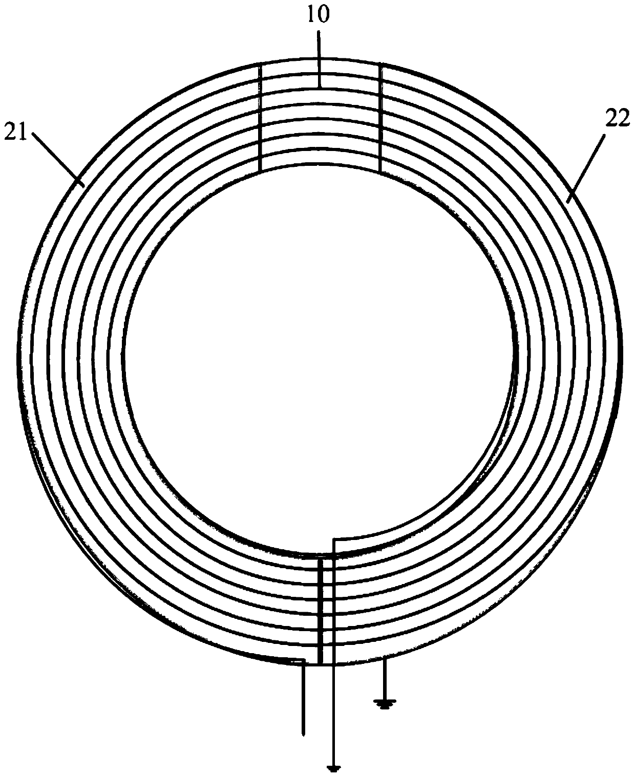
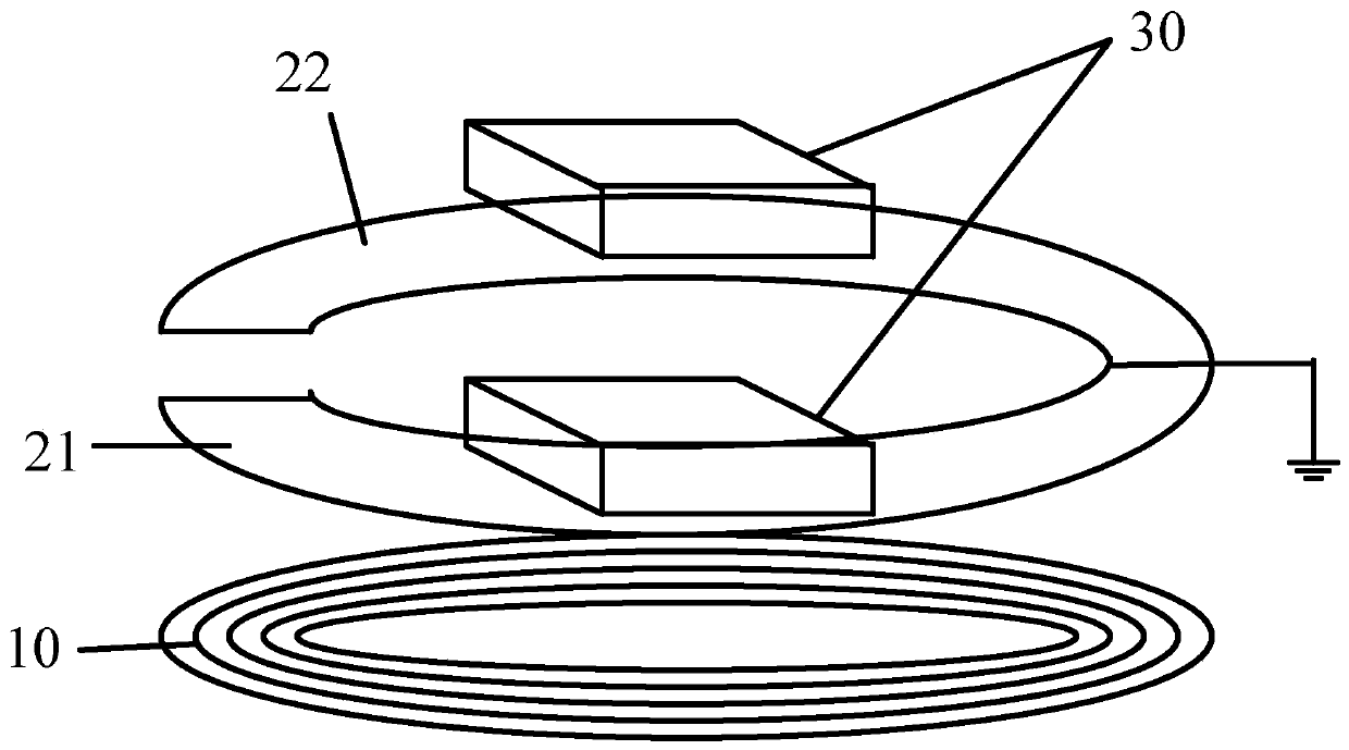
[0019] see Figure 1-2 , is a schematic diagram of the printed circuit board layout and a layered schematic diagram of the electric field shielding device that does not affect the transmission efficiency of the wireless coupling transmission coil according to the embodiment of the present invention, wherein,

[0020] Taking a four-layer printed circuit board as an example, the transmission coil 10 is located on the bottom first layer, the left semi-annular metal sheet 21 and the right semi-annular metal sheet 22 are located on the third layer above the transmission coil 10, and other electronic components 30 are on the left side. The fourth layer of the semi-annular metal sheet 21 and the right semi-annular metal sheet 22.

[0021] In a specific embodiment, the outer diameter of the left semi-annular metal sheet 21 and the right semi-annul...


PUM

PropertyMeasurementUnit
Copper thicknessaaaaaaaaaa
Diameteraaaaaaaaaa

Abstract

The invention discloses an electric field shielding device without influencing transmission efficiency of a wireless coupling transmission coil. The electric field shielding device is composed of two semi-annular metal sheets and is positioned above the transmission coil, wherein the top of a circular ring formed by the two semi-annular metal sheets is provided with a gap which is larger than one tenth of the diameter of a maximum coil, and the bottoms of the two semi-annular metal sheets are connected and grounded. According to the electric field shielding device without influencing the transmission efficiency of the wireless coupling transmission coil, electric field radiation of a wireless coupling transmission circuit is effectively reduced, and the influence of the shielding device on the wireless transmission efficiency and the wireless coupling resonance is small; and meanwhile, other circuit components can be placed above the shielding device, the circuit area of the transmission coil can be effectively reduced; finally, the whole device has the advantages of being simple in design, easy to implement and the like.

Description

technical field [0001] The invention belongs to the field of implantable medical devices, in particular to an electric field shielding device which does not affect the transmission efficiency of a wireless coupling transmission coil. Background technique [0002] In implantable medical devices, the method of transmitting data and energy through wireless coupling has been widely used. However, in the actual application process, this near-field strong coupling method is prone to generate multiple harmonics and electric field radiation. Cause the electromagnetic radiation index to exceed the standard phenomenon. In order to solve this problem, we usually choose shielding measures. Common shielding measures generally use a well-grounded metal mesh or cover to achieve electromagnetic shielding. However, this method will cause the time-varying magnetic field in the transmission coil to induce voltage on the adjacent shielded metal, thereby generating eddy currents on the metal pl...

Claims


Application Information

Patent Timeline
IPC IPC(8): G12B17/02
CPCG12B17/02H01F27/363H01F5/003H01F2038/143H02J50/10H02J2310/23H02J50/70
Inventor 黄穗曾国兴孙晓安
Owner ZHEJIANG NUROTRON BIOTECH
Learn More