Automatic constant-temperature high-definition dyeing device

A dyeing device and constant temperature technology, applied in the field of biochemical dyeing, can solve problems such as low efficiency and troublesome operation, and achieve the effects of avoiding cross-contamination, convenient removal and improving efficiency.

Pending Publication Date: 2019-09-27
ZHENGZHOU ZHONGPU MEDICAL INSTR CO LTD
View PDF5 Cites 22 Cited by
  • Summary
  • Abstract
  • Description
  • Claims
  • Application Information

AI Technical Summary

Problems solved by technology

[0006] The purpose of the present invention is to provide an automatic constant temperature high-definition dyeing device to solve the problems of troublesome operation and relatively low efficiency in the technology

Method used


Image

  • Automatic constant-temperature high-definition dyeing device
  • Automatic constant-temperature high-definition dyeing device
  • Automatic constant-temperature high-definition dyeing device

Examples


Embodiment 1

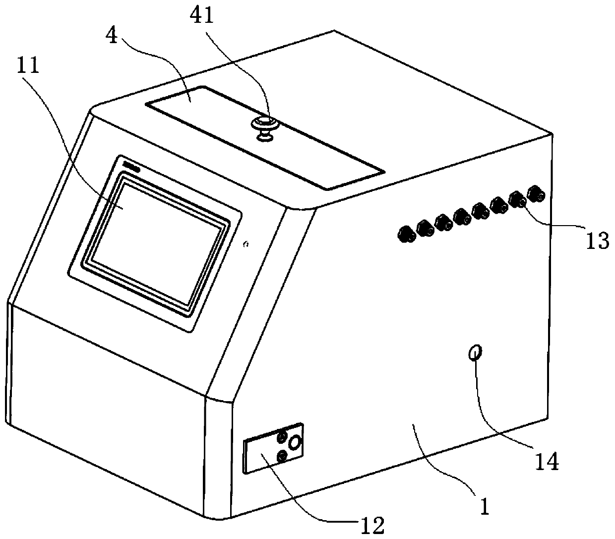
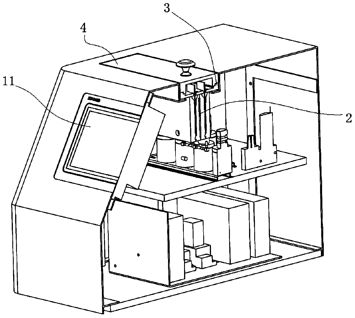
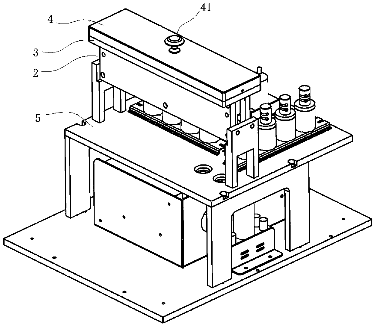
[0045] like Figure 1-Figure 13 As shown, the automatic constant temperature high-definition dyeing device includes a housing 1 and a drip dyeing assembly. The drip dyeing assembly includes several dyeing chamber units 22, and there are 12 dyeing chamber units in this embodiment. The staining chamber unit 22 is provided with a staining chamber 221 with an upper opening for placing the staining solution and for inserting the glass slide 6 loaded with the sample. The distance between the front and rear side walls of the staining cavity 221 is greater than the thickness of the glass slide 6, preferably greater than 0.5 mm, such as 0.5-1 mm.

[0046] Figure 10As shown, the left and right side walls of the staining chamber 221 are provided with slide guide grooves 2212 extending up and down. There are gaps in between. The width of the slide guide groove 2212 is preferably slightly larger than the thickness of the slide, preferably 1.2-1.5mm. The width of the slide guide groove...

Embodiment 2

[0105] The difference between this embodiment and Embodiment 1 is that in this embodiment, the liquid discharge hole and the liquid inlet hole are set independently, and no longer share one hole. The liquid discharge hole 228 is arranged at the position of the liquid inlet and outlet hole in Embodiment 1, the liquid inlet hole 227 is arranged on the side wall of the dyeing structural unit, and the liquid inlet hole is connected with the dyeing cavity of the corresponding dyeing chamber unit.

[0106] The liquid inlet hole 227 is used to connect with the liquid inlet pipeline, and the liquid inlet pipeline includes a reaction solution parallel pipeline, and the reaction solution parallel pipeline includes several reaction solution pipelines for providing different types of dyeing reaction solutions in parallel, such as respectively Reaction solution pipeline A, reaction solution pipeline B, reaction solution pipeline C, reaction solution pipeline D, reaction solution pipeline E ...

Embodiment 3

[0110] The difference between this embodiment and Embodiment 1 is that 4 rows of dyeing bin units are set in this embodiment, and 6 dyeing bin units are arranged in each row, that is, there are 24 dyeing bin units in total, and 24 dyeing bin units can be realized at a time. Staining of slides.

[0111] The four dyeing structural units are provided with two controllable constant temperature heating modules, and the two dyeing structural units share one controllable constant temperature heating module for heating.

[0112] Of course, each dyeing structural unit can also be provided with an independent controllable constant temperature heating module.

[0113] In other embodiments, 6 rows of dyeing chamber units can also be set, with a total of 36 dyeing chamber units, which can dye 36 slides at a time.


PUM

PropertyMeasurementUnit
lengthaaaaaaaaaa

Abstract

The invention relates to an automatic constant-temperature high-definition dyeing device. The device comprises a shell and a dripping-dyeing module; the dripping-dyeing module comprises multiple dyeing warehouse units, and a dyeing cavity is arranged at each dyeing warehouse unit; slide guide slots are arranged at a left sidewall and a right sidewall of each dyeing cavity; the slide guide slots guide and position the slides, a liquid inlet and drainage hole is arranged at the bottom of each dyeing warehouse unit, and the liquid inlet and drainage hole is connected with a liquid inlet and drainage pipe; the dripping-dyeing module further comprises a middle cover body and an upper cover body, and the slide insertion openings with the same amount of the dyeing warehouse units are arranged on the middle cover body, and the slide insertion openings are corresponding to the dyeing cavities one by one and used for the insertion and guidance of the slides; the upper cover body is covered at an upper side of the middle cover body, and each dyeing warehouse unit is located in the shell. Through the automatic constant-temperature high-definition dyeing device provided by the invention, the simultaneous dyeing operation on the multiple slides can be accomplished by inserting multiple slides at a time, the efficiency is greatly improved; when the slides are inserted, an operation of distinguishing the positive and the negative is unnecessary, and the operation is convenient.

Description

technical field [0001] The invention relates to the field of biochemical dyeing, in particular to an automatic constant temperature high-definition dyeing device. Background technique [0002] In the fields of hematological staining, microbiological staining, pathological staining, cytological staining, reproductive medicine staining, and nuclear chromosome staining, artificial staining or instrumental staining is usually used, but there are the following problems: [0003] In existing manual dyeing methods, different people will produce large artificial differences in results, and some dyeing operations have many steps and take up a lot of time and labor. [0004] The staining effect of the existing automatic staining instrument is not good or the reagent consumption is relatively large. Most of the staining instruments are centrifugal staining, it is troublesome to load or take the slides, and it is necessary to distinguish the front and back sides of the slides during op...

Claims


Application Information

Patent Timeline
Patent Type & Authority Applications(China)
IPC IPC(8): G01N1/31
CPCG01N1/31
Inventor 詹晓春付凤霞詹斯喻
Owner ZHENGZHOU ZHONGPU MEDICAL INSTR CO LTD
Why Eureka
Try Eureka