
Shear wall composed of corrugated steel sheets and concrete-filled steel tubular members

A technology of concrete filled steel tubes and corrugated steel plates, which is applied to building components, walls, building structures, etc., can solve the problems of difficult welding of vertical plates, low factory efficiency, affecting internal concrete filling, etc., and achieves high flexural rigidity. Good mechanical performance

Pending Publication Date: 2019-09-27
TSINGHUA UNIV
View PDF0 Cites 2 Cited by
  • Summary
  • Abstract
  • Description
  • Claims
  • Application Information

AI Technical Summary

Problems solved by technology

The shear wall composed of flat steel plate wrapped with concrete needs to support the formwork when pouring concrete, and the construction cost is high. In order to ensure the mechanical performance of the flat steel plate, it is often necessary to arrange shear connectors densely, which will affect the internal concrete. Filling, and brittle fracture cannot be avoided when the wall is damaged, and the ductility is not good
The steel pipe beam-concrete composite wall is composed of multiple C-shaped cross-section cold-formed steels welded in sequence. Naturally, the welding workload is large and the production efficiency is low, especially when the upper and lower composite walls are connected. It is difficult to weld to the plate, so it cannot be continuously penetrated, so that the internal vertical plate cannot directly transmit the axial force
The corrugated steel plate-concrete composite wall needs to be independently made of corrugated steel plates, and special through-bolts are also required. If manual assembly is used, the factory efficiency is not high. If automated and intelligent production lines are adopted, corresponding equipment needs to be further developed

Method used


Image

  • Shear wall composed of corrugated steel sheets and concrete-filled steel tubular members
  • Shear wall composed of corrugated steel sheets and concrete-filled steel tubular members
  • Shear wall composed of corrugated steel sheets and concrete-filled steel tubular members

Examples


Embodiment Construction

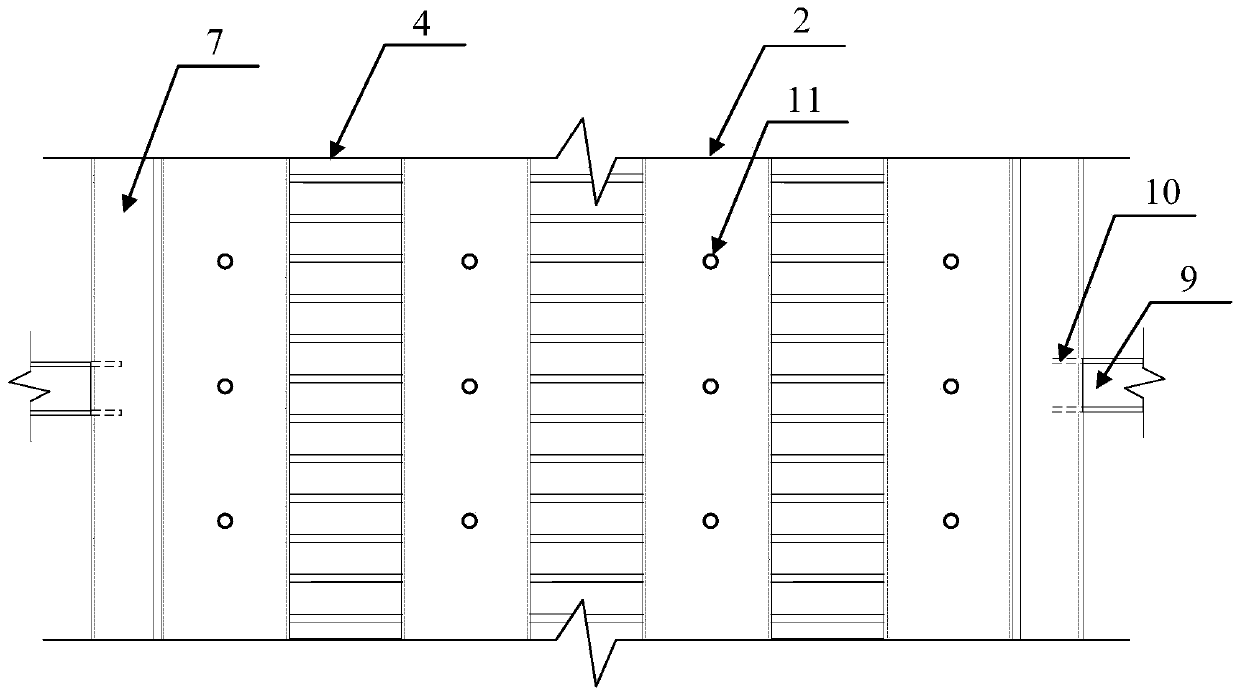
[0029] The implementation of the present invention will be described in detail below in conjunction with accompanying drawings 1 to 3, and the content is an explanation of the present invention rather than a limitation. In the picture:

[0030] 1——rectangular steel tube concrete member;

[0031] 2——Concrete steel tube members with tension bolts;

[0032] 3—Square steel pipe concrete member;

[0033] 4—corrugated steel plate;

[0034] 4-1——corrugated steel plate;

[0035] 4-2——Trapezoidal corrugated steel plate;

[0036] 4-3——rectangular corrugated steel plate;

[0037] 5 - rectangular steel pipe;

[0038] 6 - square steel pipe;

[0039] 7—C-shaped section cold-formed steel vertical edge member;

[0040] 8 - concrete;

[0041] 9——steel beam;

[0042] 10——horizontal horizontal partition;

[0043] 11——High-strength bolts.

[0044] As shown in Figures 1-2, the shear wall composed of corrugated steel plates and steel tube concrete members includes a rectangular steel tu...


PUM


Abstract

The invention relates to a shear wall composed of corrugated steel sheets and concrete-filled steel tubular members and belongs to the technical field of structural engineering. The shear wall comprises the rectangular concrete-filled steel tubular members or concrete-filled steel tubular members provided with split bolts, the corrugated steel sheets and C-shaped section cold forming sectional steel vertical edge members. The rectangular concrete-filled steel tubular members are formed in a cold roll forming mode or a welding mode. The multiple concrete-filled steel tubular members or the multiple concrete-filled steel tubular members provided with the split bolts are connected with the corrugated steel sheets in sequence in a welding mode, so that a main pressure-bearing framework of the shear wall is formed. According to the shear wall formed by directly welding the concrete-filled steel tubular members and the corrugated steel sheets, section plates can be directly connected during upper and lower shear wall splicing, the shortcoming that inner partition plates of a continuous multi-cavity shear wall fail to be connected directly during splicing, and consequentially, axial force transmission is interrupted is overcome, and the material utilization efficiency is greatly improved; and the shear wall has the advantages of high bearing efficiency, flexible plane arrangement and the like.

Description

technical field [0001] The invention relates to a shear wall composed of corrugated steel plates and steel tube concrete components, which belongs to the technical field of structural engineering. Background technique [0002] The shear wall structure has the advantages of large lateral stiffness, high bearing capacity, and good seismic performance, and is widely used in high-rise civil buildings. Reinforced concrete shear wall is the earliest applied shear wall unit, and its use is still unabated. However, due to the brittle failure characteristics of concrete materials, the ductility under earthquake is not good. Compared with reinforced concrete shear walls, steel plate shear walls have improved bearing capacity and ductility, and have good hysteretic performance and energy dissipation capacity. However, in order to give full play to the advantages of the steel plate shear wall in terms of mechanical properties and economic performance, the thickness of the steel plate s...

Claims


Application Information

Patent Timeline
IPC IPC(8): E04B2/56
CPCE04B2/56
Inventor 郭彦林李竞远朱靖申王梦争朱博莉
Owner TSINGHUA UNIV
Learn More