a disinfection cabinet

A technology for disinfection cabinets and disinfection chambers, applied in the field of disinfection cabinets, can solve problems such as limited disinfection range, different disinfection effects, and uneven distribution of ultraviolet rays, and achieve the effects of eliminating dead spots for disinfection, uniform distribution of ultraviolet rays, and improving disinfection effects

Active Publication Date: 2021-02-26
NINGBO FOTILE KITCHEN WARE CO LTD
View PDF12 Cites 0 Cited by
  • Summary
  • Abstract
  • Description
  • Claims
  • Application Information

AI Technical Summary

Problems solved by technology

The disinfection cabinet with the above structure makes the utensils to be sterilized close to the ultraviolet rays and achieves the disinfection effect by rotating the bowl rack. However, this cannot fundamentally solve the problem, because the position of the ultraviolet lamp tube is fixed, and the disinfection range it can cover is limited. Moreover, due to the uneven distribution of ultraviolet rays in the disinfection range, the disinfection effect of each position is also different. Turning the bowl rack can only make the utensils on the bowl racks sterilize after entering the disinfection range, but the utensils in the corners of the disinfection cabinet still cannot achieve the disinfection effect. , not only seriously affected the disinfection effect, but also caused the space in the disinfection cabinet to not be effectively utilized, making it inconvenient to use
[0004] In addition, during the disinfection process, some food odors and ozone remaining on the tableware will be dispersed in the disinfection cabinet. After the disinfection cabinet is opened, the odor and ozone will easily overflow into the kitchen space, causing kitchen odors and air pollution, seriously affecting the consumer experience.

Method used


Image

  • a disinfection cabinet
  • a disinfection cabinet
  • a disinfection cabinet

Examples


Embodiment Construction

[0027] The present invention will be further described in detail below in conjunction with the accompanying drawings and embodiments.

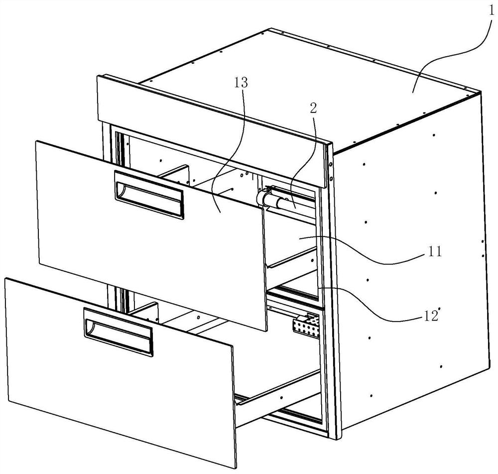
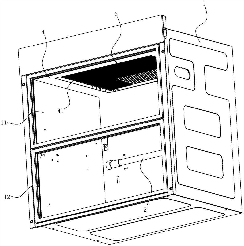
[0028] Such as Figure 1-7 As shown, the disinfection cabinet of the present embodiment includes a box body 1, an ultraviolet lamp 2 and a reflector 3. The inside of the box body 1 is hollow to form a disinfection chamber 11. The front side of the box body 1 has a front port that communicates with the disinfection chamber 11. 12. The front port 12 is provided with a door body 13 that can open or close the front port 12. The door body 13 can adopt a pull-out type, a side-turning type, and other structures. The ultraviolet lamp tube 2 of this embodiment can emit ultraviolet light and release ozone, and is used to sterilize the articles in the disinfection chamber 11 . The ultraviolet lamp tube 2 is arranged on the rear side wall of the disinfection chamber 11 .

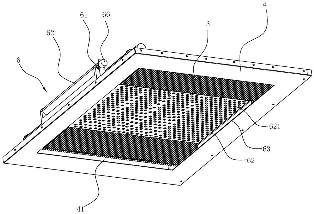
[0029] The reflector 3 of the present embodiment has a corrugated structure 30, t...


PUM


Abstract

The invention relates to a disinfection cabinet, which includes a box body with a disinfection chamber and an ultraviolet lamp tube arranged on the inner wall of the disinfection chamber. The ultraviolet lamp tube is arranged on the first inner wall of the disinfection chamber, and is characterized in that it also includes a reflective plate , the reflective plate is shaped like a ring and has a wavy structure on the surface, the reflective plate can be reciprocally rotated and arranged on the second inner wall of the disinfection chamber, and the surface of the reflective plate constitutes at least a part of the second inner wall of the disinfection chamber . In the present invention, a continuously rotating reflective plate is provided on the inner wall of the disinfection chamber, and the reflective plate has a wave-like structure, which can continuously change the position of the reflective surface with the rotation of the reflective plate, so that the UV lamp can generate The ultraviolet rays are reflected to all parts of the disinfection chamber, so that the ultraviolet rays are evenly distributed, thereby eliminating the dead angle of disinfection and improving the disinfection effect.

Description

technical field [0001] The invention relates to the technical field of kitchen appliances, in particular to a disinfection cabinet. Background technique [0002] Most of the disinfection cabinets currently on the market are high temperature or ozone disinfection. Occasionally, ultraviolet disinfection cabinets are combined with high temperature or ozone, and there are few independent ultraviolet disinfection cabinets. The reason is that the disinfection range of ultraviolet light disinfection in the cabinet is limited. It is easy to cause incomplete disinfection and has certain defects. [0003] In order to solve the above problems, the Chinese utility model patent application "rotary ultraviolet disinfection cabinet" (application number: CN201010512726.5) with the application publication number CN102451478A discloses a structure, which includes a disinfection room, an electric control room, a motor, and a rectifier. A dish rack assembly and an ultraviolet disinfection lamp...

Claims


Application Information

Patent Timeline
Patent Type & Authority Patents(China)
IPC IPC(8): A61L2/10A61L2/26
CPCA61L2/10A61L2/26A61L2202/13
Inventor 张文龙
Owner NINGBO FOTILE KITCHEN WARE CO LTD
Why Eureka
Try Eureka