
A laser optical path calibration method for marking equipment

A technology of optical path calibration and marking, applied in welding equipment, metal processing equipment, laser welding equipment, etc., can solve the problems of poor effect, time-consuming and laborious, no methods and steps, etc., and achieve simple calibration method and strong operability , the effect of improving efficiency

Active Publication Date: 2021-04-30
JIANGXI CHANGHE AVIATION IND
View PDF5 Cites 0 Cited by
  • Summary
  • Abstract
  • Description
  • Claims
  • Application Information

AI Technical Summary

Problems solved by technology

[0004] In the past, the adjustment and calibration process was only based on experience and trial, without fixed methods and steps, which was time-consuming and laborious, and the effect was not good

Method used


Image

  • A laser optical path calibration method for marking equipment
  • A laser optical path calibration method for marking equipment
  • A laser optical path calibration method for marking equipment

Examples


Embodiment Construction

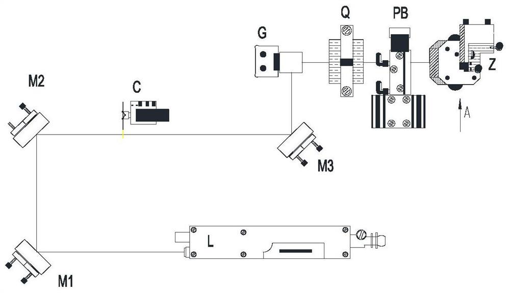
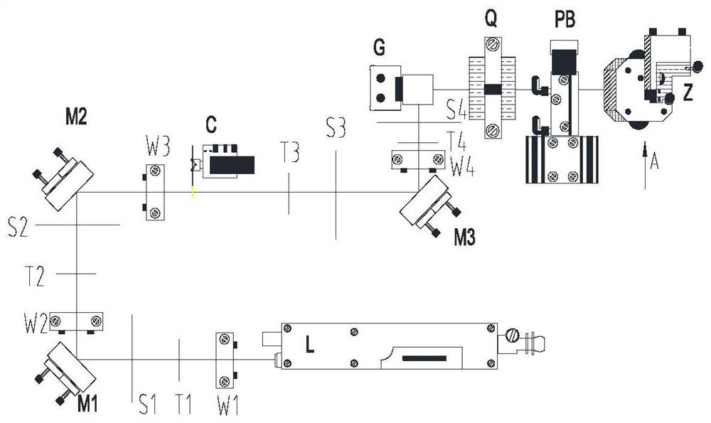
[0020] by figure 1 The marking equipment shown is an example, see figure 2 The method for calibrating the laser optical path of the marking equipment of the present invention is described, the method includes the following steps:

[0021] Step 1: Go to service mode, make sure the interlock is set and the exterior alarm light is flashing.

[0022] Step 2: Laser ignition, wear suitable laser protective glasses when igniting, the laser energy is completed at a low power (usually 330-350μs, Q switch delay).

[0023] Step 3: Move the letter mask C, the mask must be removed from the path of the laser beam.

[0024] The fourth step: rough adjustment;

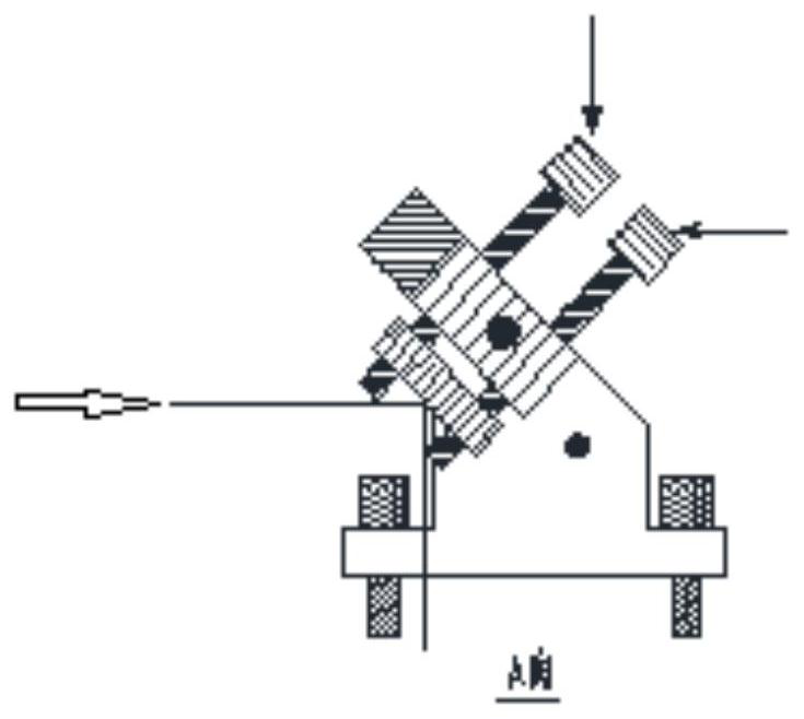
[0025] Align the laser L, ignite the laser L, and check whether the emitted laser beam hits the center of the rotating mirror M1. Loosen the three nuts of the laser L, move it to the anti-vibration base, carefully adjust the angle of the laser L, adjust the rotating mirror M1 vertically, and straighten the beam so that the beam hi...


PUM


Abstract

The invention belongs to the application field of laser equipment, and in particular relates to a method for calibrating a laser light path of a marking equipment. In the past, the adjustment and calibration process was only based on experience and trial, without fixed methods and steps, which was time-consuming and laborious, and the effect was not good. The method for calibrating the laser optical path of the marking equipment of the present invention firstly ignites the laser and moves the letter mask C out of the optical path, then roughly adjusts and straightens the laser L so that the emitted laser beam hits the center of the rotating mirror M; , the target T and the white screen S are inserted into each section of the optical path between the laser generator L and the galvanometer mirror G according to the optical path, respectively, for fine adjustment, observe the laser beam on the white screen S, and repeatedly fine-tune the rotating mirror M until The intersection point of the beam coincides with the intersection point on the white screen S; finally move the letter mask C to make it enter the path of the laser beam, and adjust the final turning mirror Z to make the effect of marking characters qualified. The calibration method is simple, the operability is strong, and the efficiency is greatly improved.

Description

technical field [0001] The invention belongs to the application field of laser equipment, and in particular relates to a method for calibrating a laser light path of a marking equipment. Background technique [0002] Laser marking equipment is a marking method that uses a high-energy-density laser to irradiate a designated part of a workpiece to vaporize the surface material or undergo a chemical reaction of color change, thereby leaving a permanent mark. Such as figure 1 As shown, the usual laser marking equipment includes laser generator L, rotating mirror M1, rotating mirror M2, letter mask C, rotating mirror M3, galvanometer mirror G, scanning mirror Q, polar beam combiner PB and final steering Mirror Z and other components. The laser light source is transmitted in the order of the above components, and finally the laser that meets the requirements is irradiated to the designated part of the workpiece, so as to mark the required characters. [0003] In the aviation fi...

Claims


Application Information

Patent Timeline
Patent Type & Authority Patents(China)
IPC IPC(8): B23K26/035
CPCB23K26/035
Inventor 刘玉成陈洋锋韩云中张银菊许立正余丹华徐正伦吴林俊
Owner JIANGXI CHANGHE AVIATION IND
Learn More