
Method for testing multiple welding residual stress components via three-dimensional optical contour method

A residual stress, three-dimensional optical technology, applied in the direction of measuring force components, measuring devices, force/torque/work measuring instruments, etc., can solve problems such as time-consuming, thick plate welding stress residual stress, limited large-size components, etc.

Active Publication Date: 2019-09-20
XI AN JIAOTONG UNIV
View PDF6 Cites 7 Cited by
  • Summary
  • Abstract
  • Description
  • Claims
  • Application Information

AI Technical Summary

Problems solved by technology

However, both of these two commonly used methods measure the surface residual stress and cannot measure the internal residual stress of the workpiece.
Other internal residual stress testing methods, such as the layer-by-layer peeling method and the crack flexibility method, can measure the uniform residual stress distribution state of thick plates, but for welding residual stress fields with large stress gradient changes, they cannot accurately measure longitudinal stress and Transverse stress gradient, and complex and cumbersome, while the neutron diffraction method is too costly, time-consuming and limited to large-scale components
The contour method can only obtain the normal stress of the cut surface in a single cutting process, but the welding stress problem of thick plates often involves residual stress in multiple directions

Method used


Image

  • Method for testing multiple welding residual stress components via three-dimensional optical contour method
  • Method for testing multiple welding residual stress components via three-dimensional optical contour method
  • Method for testing multiple welding residual stress components via three-dimensional optical contour method

Examples


Embodiment

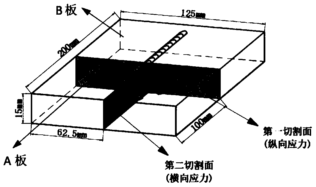
[0056] In this embodiment, Q345 low-carbon steel is selected for the experiment, and ordinary tungsten inert gas welding (TIG) is used. The size of the Q345 test plate is 200mm*125mm*15mm. The weld is located in the center of the test plate, starting from 40mm from one end of the test plate, the length of the weld is 120mm, and the actual width of the weld is about 10mm. Consider performing stress-relief annealing treatment on the test plate. The process parameters of stress-relief annealing are holding temperature 590°C and heating rate 100°C·h -1 , The cooling method is furnace cold, and the holding time is 3h. Welding process parameters: welding current 230A, welding voltage 17.5V, shielding gas 15L min -1 , welding speed 15cm·min -1 .

[0057] A method for testing multiple welding residual stress components by three-dimensional optical profilometry, the steps of which are as follows:

[0058] Step 1: Before welding, perform stress relief annealing on the test plate, t...


PUM


Abstract

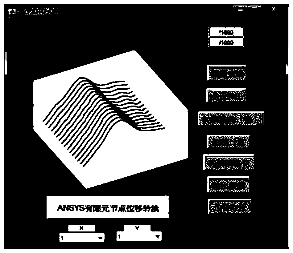
The invention relates to a method for testing multiple welding residual stress components via a three-dimensional optical contour method. Pretreatment is carried out before welding; and after welding, a low speed wire is used to cut a tested plate for multiple time, the primary cutting direction is vertical to the weld seam direction of the test plate, and cutting is carried out along the middle cross section. XJTU-OM scanning is carried out on cutting planes of the test plate, and calculated measurement point cloud data is obtained; and an established data processing platform is used to carry out positive conversion, de-noising, displacement calculating, discretion, and boundary condition output on the point cloud data. The stress is calculated and analyzed to obtain vertical residual stress distribution of primary cutting. The secondary cutting direction is vertical to the first cutting direction and along the middle cross section, the same scanning and data processing are carried out on the cutting surface contour after secondary cutting, the stress is calculated by taking the secondary cutting plane contour data as boundary conditions, and stress elasticity calculation of the secondary cutting plane is realized. Thus, the method has theoretical and engineering significance in testing the multiple residual stress components of a welding member.

Description

technical field [0001] The invention relates to the technical field of engineering measurement residual stress, in particular to a method for testing multiple welding residual stress components by three-dimensional optical profilometry. Background technique [0002] Since the development of residual stress testing, there have been dozens of testing methods for different working conditions, which are divided into mechanical (destructive) measurement methods and physical (non-destructive) measurement methods, each of which has its own advantages and disadvantages. Destructive methods include blind hole method, strip cutting method, elastic deformation method, etc. Among them, the small hole method is used more. The small hole release method is suitable for measuring welded components with large stress gradient changes due to its simple operation, and it is also suitable for measuring The advantages of small destructive components have been widely used in recent years, and it h...

Claims


Application Information

Patent Timeline
IPC IPC(8): G01L5/00G01L5/16
CPCG01L5/0047G01L5/166
Inventor 殷咸青何向前牛靖梁晋张建勋
Owner XI AN JIAOTONG UNIV
Learn More