
Transmission device capable of eliminating transmission clearance and clearance eliminating method thereof

A technology of speed change and clearance, applied in hoisting devices, portable lifting devices, components with teeth, etc., can solve the problems of difficult transmission accuracy, many transmission components, complex structure, etc., to reduce wear and improve accuracy. Longevity and damage reduction effect

Active Publication Date: 2019-09-20
CHENGDU ZHONGLIANGCHUANGONG TECH CO LTD
View PDF15 Cites 12 Cited by
  • Summary
  • Abstract
  • Description
  • Claims
  • Application Information

AI Technical Summary

Problems solved by technology

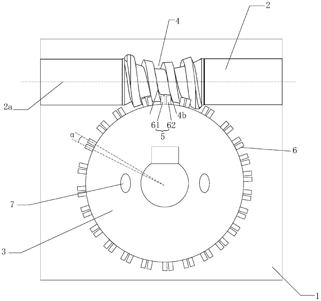
[0015] Aiming at the shortcomings of the existing structure for eliminating backlash due to the large number of transmission elements, large volume and complex structure, it is difficult to apply to the transmission device of the servo drive system requiring high transmission precision, large load capacity and compact structure. The present invention provides a The speed change device that can eliminate the transmission gap, during the transmission process of the speed change device, the worm teeth defined by at least two rolling elements are in line contact with the tooth surfaces on both sides of the worm track at least in part, so that the two The abutment between the rolling elements and the tooth surfaces on both sides of the wormway avoids the tooth backlash, thereby eliminating the return error during the transmission process, avoiding the impact between the teeth, improving the stability of the transmission, and reducing the sliding friction through the rotation of the rolling elements. Converted to relative rolling friction, reducing tooth surface wear and improving precision life

Method used


Image

  • Transmission device capable of eliminating transmission clearance and clearance eliminating method thereof
  • Transmission device capable of eliminating transmission clearance and clearance eliminating method thereof
  • Transmission device capable of eliminating transmission clearance and clearance eliminating method thereof

Examples


Embodiment 1

[0054] This embodiment discloses a speed change device, which can also be a speed change device that can eliminate transmission gaps, and the device can be realized by the device of the present invention and / or other replaceable components. For example, the device of the present invention is realized by using various components in the device of the present invention. The entire and / or partial contents of the preferred implementations of other embodiments may be used as supplements to this embodiment unless conflicts or contradictions are caused.

Embodiment approach

[0055] According to a preferred embodiment, a speed change device capable of eliminating transmission backlash at least includes a worm 2 and a worm wheel 3 arranged in a casing 1 with axes different from each other. Preferably, as figure 1 As shown, the box body 1 is provided with at least two openings, one opening is located at one axial end of the worm 1 , and is used for connecting devices such as servo drives to the worm 1 . The worm wheel 2 is also provided with an opening at one axial end thereof, and the opening is used for connecting with a shaft coupling. Preferably, the axes are out of plane means that the worm axis 3a and the worm axis 2a are out-of-plane straight lines, the worm axis 2a and the worm axis 3a are not on the same plane, neither intersecting nor parallel. Preferably, the worm axis 2a and the worm wheel axis 3a are orthogonal to each other. Through this arrangement, the friction between the worm gear 5 and the wormway 4 can be reduced, and a larger t...

Embodiment 2

[0066] This embodiment discloses a speed change device, which can be realized by the device of the present invention and / or other replaceable components. For example, the device of the present invention is realized by using various components in the device of the present invention. The entire and / or partial contents of the preferred implementations of other embodiments may be used as supplements to this embodiment unless conflicts or contradictions are caused.

[0067] A speed change device, preferably, such as figure 1As shown, the box body 1 is provided with at least two openings, one opening is located at one axial end of the worm 1 , and is used for connecting devices such as servo drives to the worm 1 . The worm wheel 2 is also provided with an opening at one axial end thereof, and the opening is used for connecting with a shaft coupling. Preferably, the axes are out of plane means that the worm axis 3a and the worm axis 2a are out-of-plane straight lines, the worm axis...


PUM


Abstract

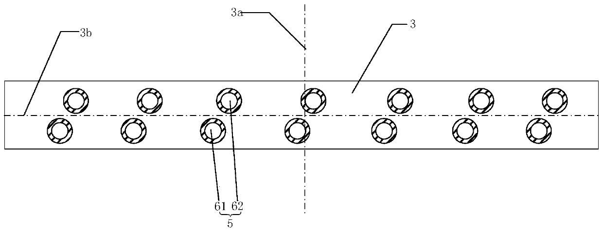
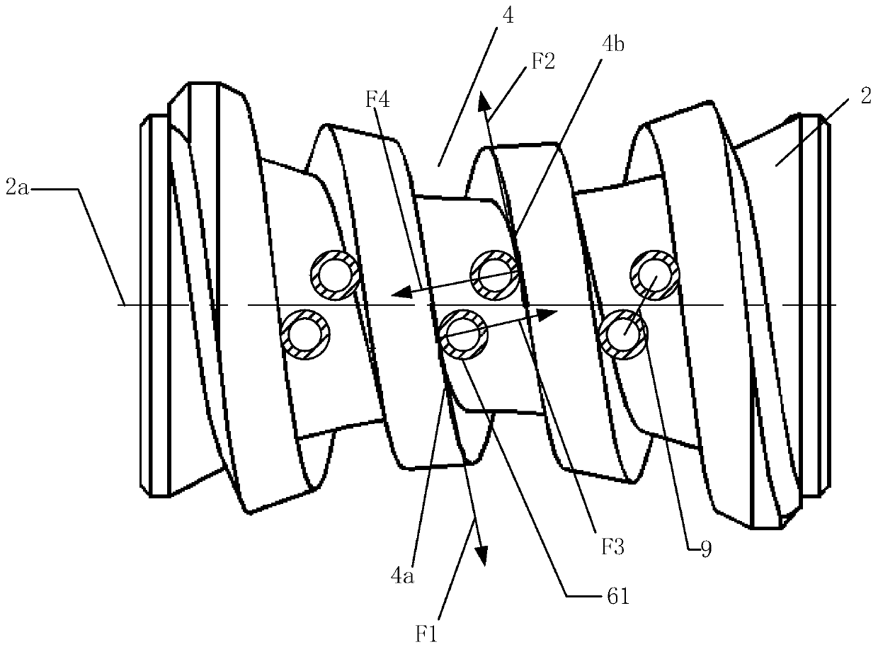
The invention relates to a transmission device capable of eliminating a transmission clearance and a clearance eliminating method thereof. The transmission device at least comprises a worm rod and a worm gear which are arranged in a box body, wherein the axes of the worm rod and the worm gear are on different planes; detachable worm teeth which can be engaged with worm threads of the worm rod are arranged on the worm gear in the peripheral direction at intervals; the worm gear comprises at least two discs which are attached to each other in the axial direction; rolling bodies distributed in the peripheral direction at intervals are separately arranged at the radial outer sides of the at least two discs; at the condition that the worm rod and / or the worm gear rotate around the axis, the worm threads are engaged with the worm teeth limited by the rolling bodies, which are adjacent to each other in the axial direction and have inclusion angles, of the at least two discs; and the rolling bodies, at the two sides of the axis of the worm rod, of the worm teeth separately revolve in a manner that the rolling bodies can be always in linear contact with the teeth surfaces at the two sides of the worm threads through the adjustment of the inclusion angles and the connecting lines of the axes of every two rolling bodies are crossed with the axis of the worm rod in a non-perpendicular manner.

Description

technical field [0001] The invention relates to the technical field of mechanical transmission, and relates to a speed change device, in particular to a speed change device capable of eliminating a transmission gap and a method for eliminating the gap. Background technique [0002] The worm drive is used in occasions where the two shafts are interlaced, the transmission ratio is large, the transmission power is not too large, or the intermittent work. Because of the advantages of stable transmission, low noise, small impact load, and self-locking, it is used as a mechanical transmission. The main transmission mode is often used in the speed change device. However, in order to form a lubricating oil film between the meshing tooth profiles of ordinary worm drives and avoid gear teeth being stuck due to friction, heat and expansion, there must be a gap between the two non-working tooth profiles of the conjugate teeth. This gap is called Tooth side clearance, referred to as sid...

Claims


Application Information

Patent Timeline
Patent Type & Authority Applications(China)
IPC IPC(8): F16H55/24F16H55/08F16H55/12F16H55/14
CPCF16H55/08F16H55/12F16H55/14F16H55/24
Inventor 邓星桥
Owner CHENGDU ZHONGLIANGCHUANGONG TECH CO LTD
Learn More