
Part distributing device

A shunting device and parts technology, applied in the field of parts shunting device, can solve problems such as legacy, stuck product, product rebound, etc., achieve the effect of simple structure, low production cost, and avoid shunting dead angle

Pending Publication Date: 2019-09-20
SICHUAN RUITENG ELECTRONICS
View PDF0 Cites 0 Cited by
  • Summary
  • Abstract
  • Description
  • Claims
  • Application Information

AI Technical Summary

Problems solved by technology

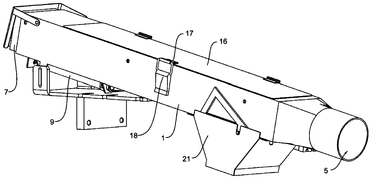
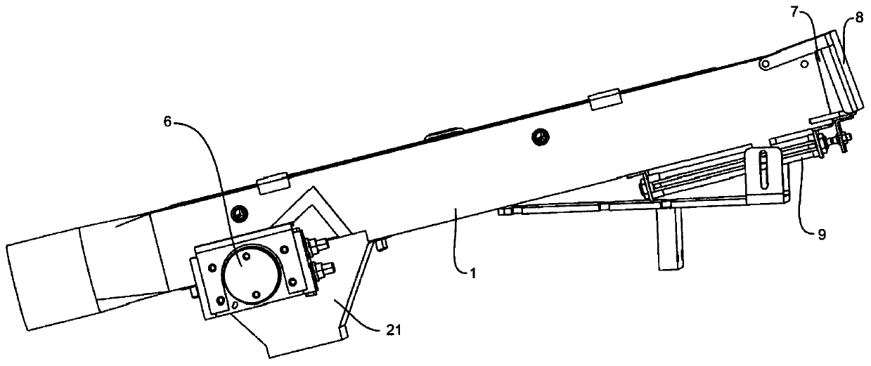
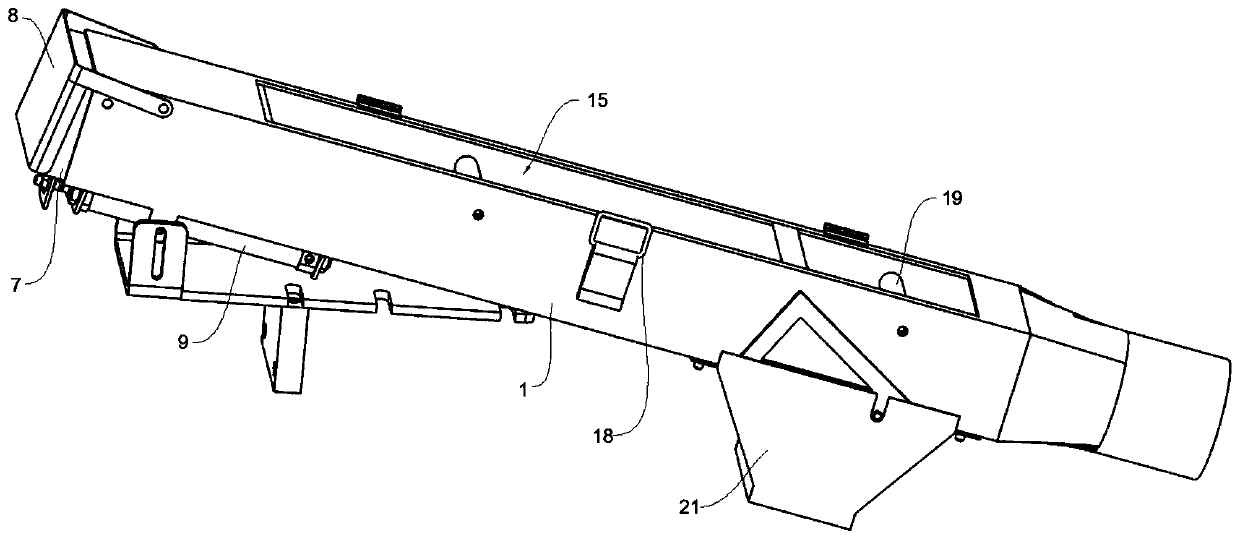
[0003] The purpose of the present invention is to provide a part diverting device, which aims to solve the problem that in the existing diverting device, substandard products are diverted in the way of left and right diversion in special-shaped pipes, which is easy to cause product rebound, stuck products and Problems arising from product legacy

Method used


Image

  • Part distributing device
  • Part distributing device
  • Part distributing device

Examples


Embodiment Construction

[0030] In order to make the purpose, technical solutions and advantages of the embodiments of the present invention clearer, the technical solutions in the embodiments of the present invention will be clearly and completely described below in conjunction with the drawings in the embodiments of the present invention. Obviously, the described embodiments It is a part of embodiments of the present invention, but not all embodiments. The components of the embodiments of the invention generally described and illustrated in the figures herein may be arranged and designed in a variety of different configurations.

[0031] In the description of the present invention, it should also be noted that, unless otherwise clearly specified and limited, the terms "setting", "installation", "connection" and "connection" should be understood in a broad sense, for example, it may be a fixed connection, It can also be detachably connected or integrally connected; it can be directly connected or ind...


PUM


Abstract

The invention relates to the technical field of distributing devices, in particular to a part distributing device comprising a distributing pipe, a distributing opening and a distributing plate. The distributing pipe is a rectangular straight through pipe and is arranged obliquely. The upper end of the distributing pipe is provided with a feed inlet, and the lower end of the distributing pipe is provided with a discharge outlet. The feed inlet in the upper end of the distributing pipe is connected to an outlet of part forming equipment. The distributing opening is formed in the position, close to the discharge outlet, of the distributing pipe and is located in the pipe wall of the lower side of the distributing pipe. The distributing plate is rotationally connected to the distributing opening and is used for blocking or opening the distributing opening, and a distributing channel toward the feed inlet is formed when the distributing opening is opened. Through the part distributing device, the problems that in an existing distributing device, rejects are distributed in an irregular-shaped pipe in a left-right distributing mode, and product bounces, product clamping, product leaving and other conditions are liable to occur in the distributing process can be solved.

Description

technical field [0001] The invention relates to the technical field of flow dividers, in particular to a part flow divider. Background technique [0002] After the stamping parts are processed, defect inspection of the parts is required in the part forming equipment, mainly to inspect the defects such as "empty riveting", "crushing" and "foreign matter entry" formed in the production process. The detection device is in When a defect is detected in the part, the splitter plate will automatically switch when the part is transported in the splitter tube and the parts will be led out from the splitter port, thereby separating the unqualified products; at the same time, the splitter can also be performed during the adjustment of the punching machine. The currently used splitter adopts the way of splitting left and right. The splitter pipe is a special-shaped tube. The distance between the splitter plate of the device and the outlet of the part is relatively close, and there is an...

Claims


Application Information

Patent Timeline
Patent Type & Authority Applications(China)
IPC IPC(8): B07C5/36B07C5/34B21C51/00
CPCB07C5/362B07C5/34B21C51/00
Inventor 王康李富
Owner SICHUAN RUITENG ELECTRONICS
Learn More