Thin type floor heating system mounting structure

A technology for installation structure and floor heating, which is applied to heating methods, building structures, hot water central heating systems, etc. It can solve the problems of high building floor loss, slow construction progress, and large energy consumption, etc., and achieve the reduction of building floor height loss , reduce construction time, and reduce the effect of high energy consumption operation time

Inactive Publication Date: 2019-09-17
四川赛特威斯科技有限公司
View PDF6 Cites 1 Cited by
  • Summary
  • Abstract
  • Description
  • Claims
  • Application Information

AI Technical Summary

Problems solved by technology

[0004] The purpose of the present invention is to provide a thin floor heating installation structure and its preparation method to solve the problem that the construction progress of the existing wet paving method is slow, and the heat is transferred to the ground decoration layer through layers of heat-conducting medium layers during the transfer process. It is easy to cause local uneven heating, low heating efficiency, and large energy consumption, and the high floor of the building is high in loss, which can easily cause the house to feel oppressed

Method used


Image

  • Thin type floor heating system mounting structure

Examples


Embodiment 1

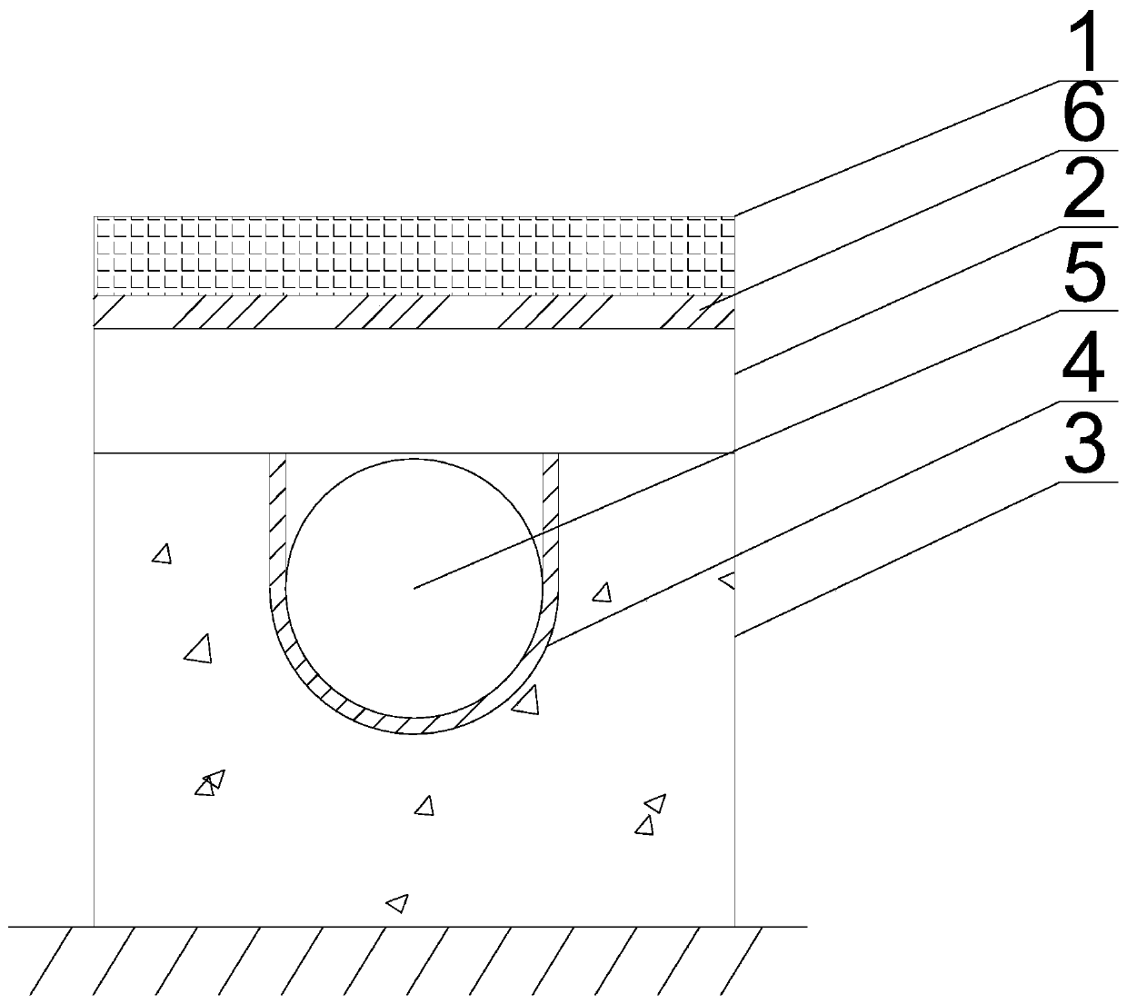
[0024] A thin floor heating installation structure, comprising a floor decoration layer 1, a heat dissipation plate 2, and an insulation layer 3 arranged sequentially from top to bottom, the heat insulation layer 3 is arranged on the concrete floor surface layer, and the heat dissipation plate 2 is provided with There are several U-shaped grooves 4, and the U-shaped grooves 4 are embedded in the insulation layer 3. The floor heating water pipes 5 are arranged in the U-shaped grooves 4. The material of the ground decoration layer 1 is a ceramic sheet, and the ground decoration layer 1 is bonded on the heat dissipation plate 2 through the heating special adhesive 6, and the heat dissipation plate 2 is covered on the insulation layer 3. The heating special adhesive 6 includes the following components in parts by weight: special cement 52 4 parts, 4 parts of quartz sand, 8 parts of cellulose ether, 6 parts of redispersible latex powder, 6 parts of plasticizer and 4 parts of starch ...

Embodiment 2

[0027] In this embodiment, on the basis of Embodiment 1, further, the firing press for the ground decoration layer 1 is 10,000 tons, and the firing temperature is 1230°C. machine, the firing temperature of 6000-7000 ℃, the density and compression resistance of the ceramic thin plate fired by the present invention is stronger than that of traditional ceramic tiles, so the thermal conductivity is higher, and the thickness is only 4-6mm, compared with traditional ceramic tiles. The tiles are lighter and thinner, which can reduce the difficulty of construction during the construction process, reduce energy consumption, and save costs.

Embodiment 3

[0029] In this embodiment, on the basis of Embodiment 1, further, the special heating adhesive 6 includes the following components in parts by weight: 51 parts of special cement, 4 parts of quartz sand, 9 parts of cellulose ether, redispersible 8 parts of latex powder, 7 parts of plasticizer and 4 parts of starch ether. Compared with cement mortar, the heating adhesive is used in less amount, faster in forming, can effectively shorten construction time, improve construction efficiency, and is thicker than cement mortar The mortar is much thinner, which is beneficial to improve the heating efficiency.


PUM


Abstract

The invention discloses a thin type floor heating system mounting structure, and relates to the technical field of floor heating system mounting structures. The thin type floor heating system mounting structure comprises a floor decoration layer which is manufactured through a thin ceramic board, a heat dissipating plate which is connected through a special adhering agent for heating, and a heat preserving layer. With the adoption of the thin type floor heating system mounting structure, more than 50% of thickness of the constructed surface can be saved, and the good effect of 'decreasing three and adding one' is achieved; decreasing three is namely decreasing the energy consumption of a floor heating system, reducing the loss of housing story, and reducing the overall construction period; and adding one is adding the temperature increasing temperature of the floor heating system.

Description

technical field [0001] The invention relates to the technical field of floor heating installation structures, in particular to a thin floor heating installation structure. Background technique [0002] Floor heating is the abbreviation of floor heating through radiation. At present, it is most commonly used as water floor heating. Water floor heating refers to the installation of thin hot water pipes under the floor, and the floor that continuously emits heat to the indoor space by injecting low-temperature hot water into the pipes and continuously circulating them back and forth. Compared with the room temperature adjusted by the air conditioner, the room temperature of the room with floor heating increases from bottom to top as the height increases, and the temperature gradually decreases, giving people a comfortable feeling of warming the feet and cooling the head, which is more in line with the physiological requirements of the human body; In contrast, the radiator and ...

Claims


Application Information

Patent Timeline
Patent Type & Authority Applications(China)
IPC IPC(8): F24D3/12F24D19/02E04F15/02E04F15/18
CPCE04F15/02E04F15/18F24D3/12F24D19/02Y02B30/00
Inventor 朱月辉刘思琪
Owner 四川赛特威斯科技有限公司
Why Eureka
Try Eureka