Combined lens composed of lens and reflecting mirror, and automobile lamp module for combined lens

A technology of combining lenses and reflectors, applied in the direction of headlights, motor vehicles, road vehicles, etc., can solve the problems of unfavorable product molding, lengthening of the front and rear length of the lights, space limitations of the lights, etc., to avoid the limitation of the space of the lights, Adjustability enhancement, reducing the effect of convergence

Pending Publication Date: 2019-09-17
HASCO VISION TECHNOLOGY CO LTD
View PDF8 Cites 2 Cited by
  • Summary
  • Abstract
  • Description
  • Claims
  • Application Information

AI Technical Summary

Problems solved by technology

[0005] The defect of the above lamp system is that the first focal point, the second focal point and the lens of the quasi-ellipsoid reflective surface are arranged in a straight line, resulting in long front and rear dimensions, and the spatial structure of the lamp is limited
[0006] In addition, the plano-convex lens is thicker, which is not conducive to product molding, especially more and more lenses are molded by plastic injection molding. The thicker the lens, the longer the molding time and cooling time, and the lens is also easily deformed by cooling, resulting in unstable focal length; However, if the thickness of the lens is reduced, the focal length will become longer, which will also lead to the lengthening of the front and rear length of the lamp, which will limit the space of the lamp

Method used


Image

  • Combined lens composed of lens and reflecting mirror, and automobile lamp module for combined lens
  • Combined lens composed of lens and reflecting mirror, and automobile lamp module for combined lens
  • Combined lens composed of lens and reflecting mirror, and automobile lamp module for combined lens

Examples


Embodiment Construction

[0054] The present invention will be further described below in conjunction with the accompanying drawings and specific embodiments.

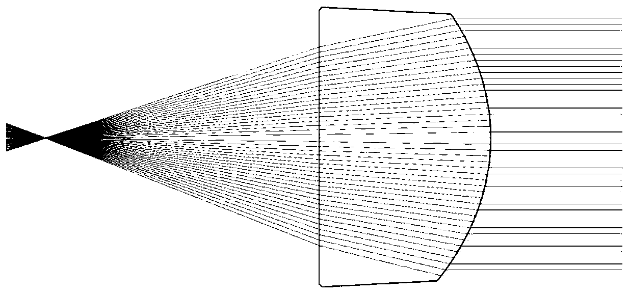
[0055] see figure 1, the light emitted by the lens from its focal point is refracted twice and then exits as parallel light, which is the prior art.

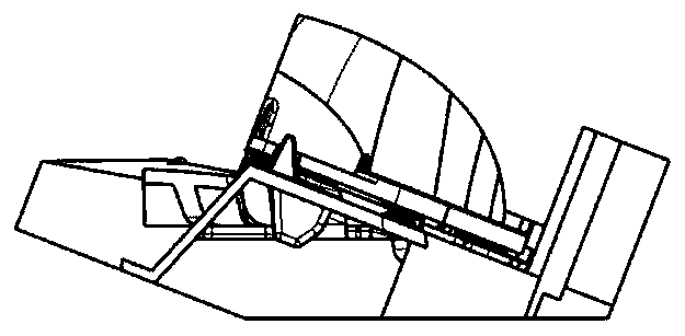
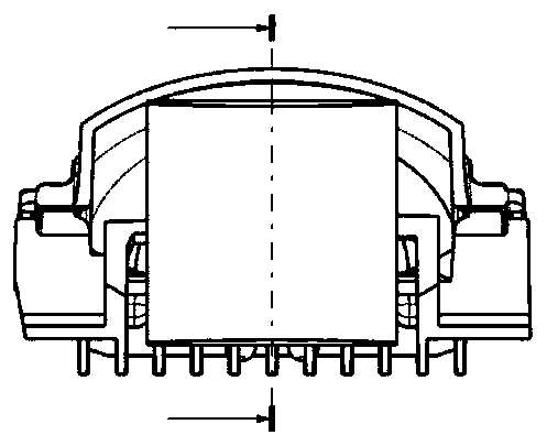
[0056] Figure 2a-Figure 2d It is a car light module composed of lenses and reflectors in the prior art, wherein the light source 1 is set at the first focus of the reflective surface of the ellipsoidal surface of the reflector 2, and converges near the second focus, and the ellipsoidal surface The second focal point is set at the focal point of the plano-convex lens 4 . If it is a car lighting system that needs a cut-off line of light and shade, such as a low-beam lighting system, a light baffle 3 is provided at the focus of the plano-convex lens to form a light-dark dividing line for lighting, such as image 3 shown. It can be found that the first focal point, the second focal point and the...


PUM


Abstract

The invention relates to a combined lens composed of a lens and a reflecting mirror. The combined lens composed of the lens and the reflecting mirror at least comprises one lens and one reflecting mirror. From a reverse light path, parallel light is subjected to twice of refraction of an incident face and an exit face of the lens, and converges at one point after being subjected to once of reflecting of the reflecting mirror, and the point is the focal point of the combined lens; the distance between the lens and the reflecting mirror is smaller than the focal distance of the lens; the lens can be a convex lens or a concave lens; the reflecting mirror can be a convex mirror, a plane mirror or a concave mirror; and meanwhile, for the traditional lens, the position of the focal point is controlled through two optical faces including the incident face and the exit face, under the condition with the same focal length, the thickness of the common lens is relatively large, and in addition, the direction of optical axis is generally the center line of the lens. For the combined lens, the focal length of the combined lens is determined at least through the incident face and the exit face of the lens and the reflecting face of the reflecting mirror, so that the thickness of the lens can be reduced, and the position of the focal point and the direction of the optical axis also can be flexibly set.

Description

technical field [0001] The invention relates to a vehicle lamp module, specifically, a combined lens composed of a lens and a reflector and the vehicle lamp module. Background technique [0002] The lens used in the existing car light system is generally a plano-convex lens. The parallel light is refracted twice through the outer surface and the inner surface of the plano-convex lens and converges at one point, that is, the focal point, such as figure 1 shown. [0003] As shown in Figure 2 of the existing car light system, the light source 1 is set at the first focal point of the quasi-ellipsoid reflective surface of the reflector 2, and converges near the second focal point, and the second focal point of the quasi-ellipsoidal surface is set on the plano-convex lens 4 of focus. If it is a car lighting system that needs a cut-off line of light and shade, such as a low-beam lighting system, a light baffle 3 is provided at the focus of the plano-convex lens to form a light-da...

Claims


Application Information

Patent Timeline
Patent Type & Authority Applications(China)
IPC IPC(8): F21S41/20F21S41/30F21S43/40F21S41/675F21W107/10
CPCF21S41/20F21S41/30F21S43/40F21S41/675F21W2107/10F21S41/323F21S41/147F21S41/255F21S41/321F21S41/365F21S41/275
Inventor 张洁
Owner HASCO VISION TECHNOLOGY CO LTD
Why Eureka
Try Eureka