
TCO (transparent conductive oxide) conducting film plating device and plating process of SHJ (silicon heterojunction) solar battery

A solar cell and coating device technology, which is applied in metal material coating process, circuit, photovoltaic power generation, etc., can solve obstacles to the commercialization and application of high-efficiency SHJ solar cells, complicated equipment structure and process, and constraints on solar cell manufacturing enterprises Problems such as equipment selection and cost control, to achieve the effect of wide application prospects and economic value, high stability and low cost

Pending Publication Date: 2019-09-17
ZHONGWEI NEW ENERGY CHENGDU CO LTD
View PDF5 Cites 0 Cited by
  • Summary
  • Abstract
  • Description
  • Claims
  • Application Information

AI Technical Summary

Problems solved by technology

This method can achieve good interface transmission to a certain extent, but its equipment structure and process are relatively complicated, which restricts the equipment selection and cost control of solar cell manufacturers, and seriously hinders the commercialization and application of high-efficiency SHJ solar cells.

Method used


Image

  • TCO (transparent conductive oxide) conducting film plating device and plating process of SHJ (silicon heterojunction) solar battery
  • TCO (transparent conductive oxide) conducting film plating device and plating process of SHJ (silicon heterojunction) solar battery
  • TCO (transparent conductive oxide) conducting film plating device and plating process of SHJ (silicon heterojunction) solar battery

Examples


Embodiment Construction

[0025] The technical solution of the present invention will be further described in detail below in conjunction with the accompanying drawings, but the protection scope of the present invention is not limited to the following description.

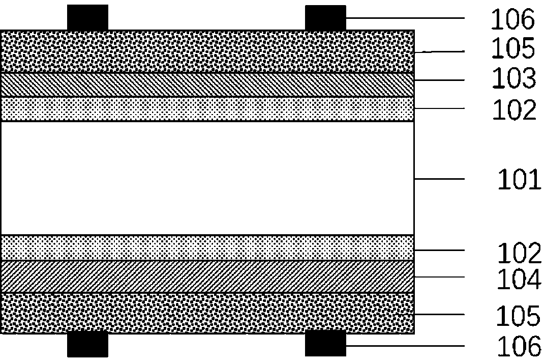
[0026] Such as figure 1 Shown is the SHJ solar cell in the prior art. During manufacture, the solar cell is based on n-type single crystal silicon wafer 101, firstly surface textured and chemically cleaned to form a clean pyramidal light-limiting structure; then plasma chemical vapor deposition (PECVD), metal Thermal catalytic chemical vapor deposition (Cat-CVD), hot wire chemical vapor deposition (Hot-wire CVD) and other methods deposit intrinsic silicon-based film 102 and n-type doped silicon-based film 103 on the front surface of silicon wafer 101. Deposit the intrinsic silicon-based film 102 and the p-type doped silicon-based film 104 stacked on the back; then deposit oxide transparent conductive film on the stacked n-type doped silico...


PUM


Abstract

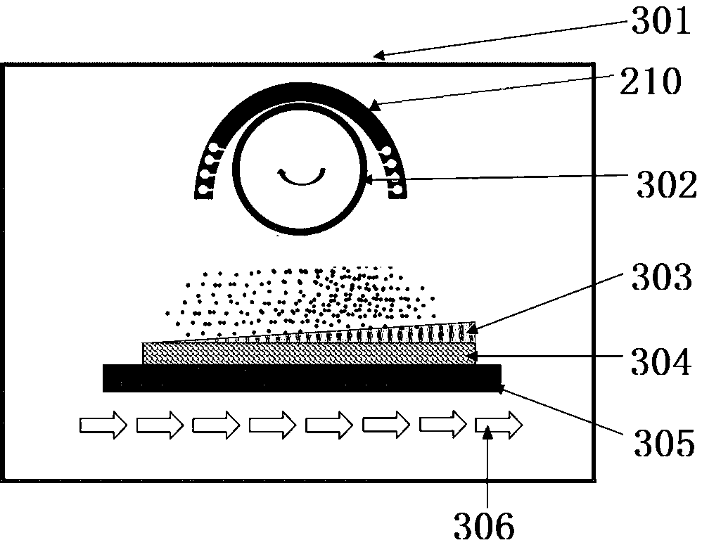
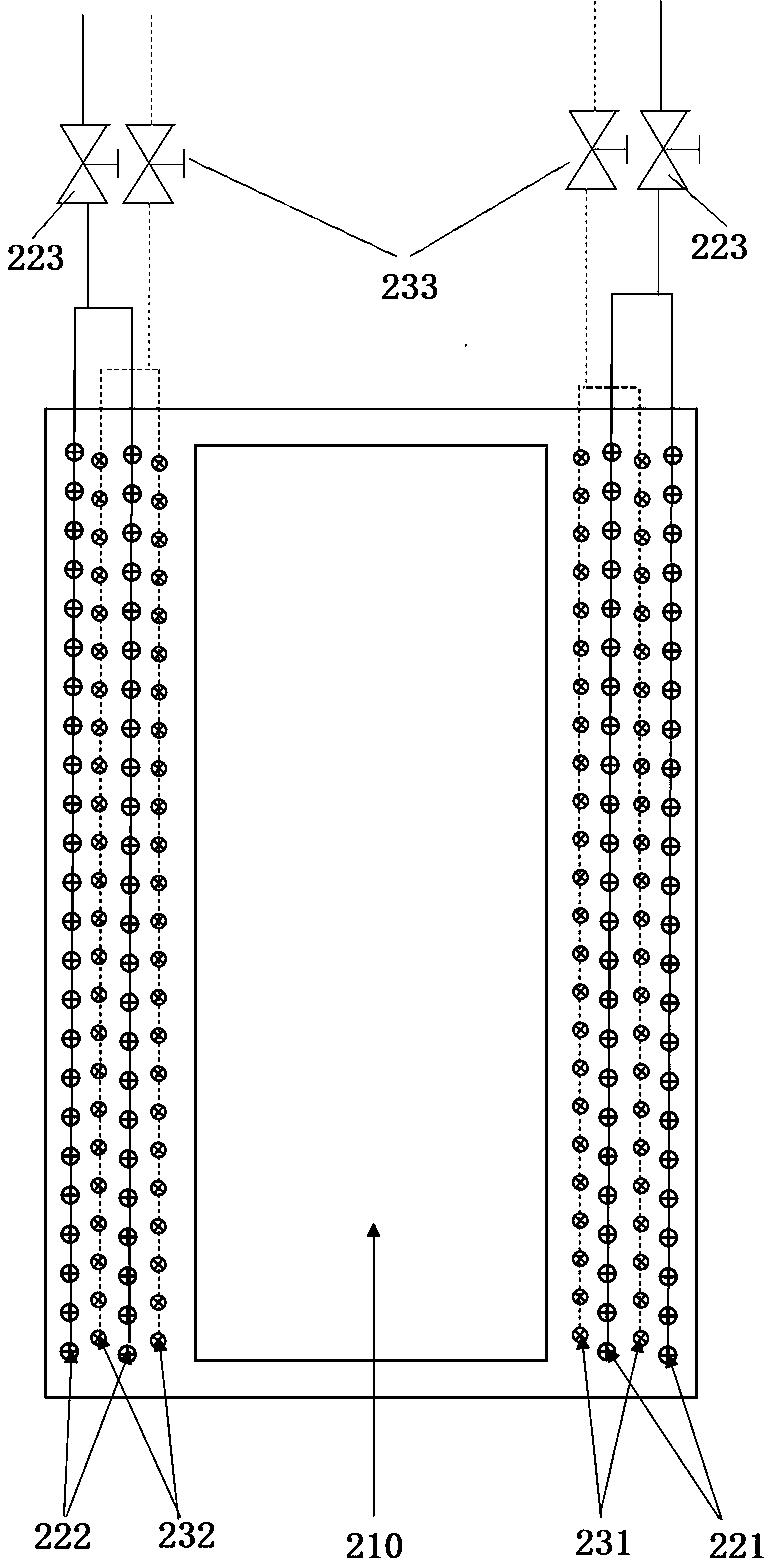
The invention discloses a TCO (transparent conductive oxide) conducting film plating device and a TCO conducting film plating process of an SHJ (silicon heterojunction) solar battery, and relates to the solar battery manufacture technology field. The TCO conducting film plating device comprises a vacuum chamber, wherein a mechanical conveying device is arranged in the vacuum chamber, a cathode structure is arranged above the mechanical conveying device, the cathode structure comprises a cathode device, and two sets of process gas control systems which independently perform control are respectively arranged on two sides of the cathode structure. The TCO conducting film plating process is a process of implementing film plating by using the above TCO conducting film plating device, and includes steps: respectively adjusting the two independent process gas control systems to provide different oxygen flow rates, forming plasma areas different in oxygen content on the two sides of the cathode device, and sequentially performing sputter plating on a workpiece in the two plasma areas different in oxygen content when the workpiece moves along with the mechanical conveying device. The TCO conducting film plating device and the TCO conducting film plating process of the SHJ solar battery can achieve differentiation film plating design under the condition of using the same target material and the same equipment, improve photoelectric converting efficiency of the SHJ solar battery, are low in cost and high in stability, are compatible with an existing film plating technology, and have wide application prospects and high economic value.

Description

technical field [0001] The invention relates to the technical field of solar cell preparation, in particular to a TCO conductive film coating device and coating process for SHJ solar cells. Background technique [0002] Solar cell power generation (photovoltaic power generation) has the characteristics of small regional differences, huge reserves, safety, no pollution, and inexhaustible resources. It has become the main force of new energy and renewable energy technologies in the 21st century. As of the end of 2018, the cumulative global installed capacity has exceeded 400GW, becoming the main force of new energy. [0003] SHJ solar cell (silicon heterojunction solar cell) is a high-efficiency solar cell technology, also known as HIT R Battery. The battery uses an n-type single crystal silicon wafer as a substrate, and an intrinsic silicon-based film, an n-type doped silicon-based film stack and an oxide transparent conductive film (TCO) are sequentially arranged on the fr...

Claims


Application Information

Patent Timeline
Patent Type & Authority Applications(China)
IPC IPC(8): C23C14/35C23C14/34C23C14/08C23C14/56H01L31/18
CPCC23C14/352C23C14/3407C23C14/56C23C14/086C23C14/083C23C14/0063H01L31/1804Y02E10/547Y02P70/50
Inventor 石建华孟凡英刘正新张丽平杜俊霖韩安军卞剑涛谢毅
Owner ZHONGWEI NEW ENERGY CHENGDU CO LTD
Learn More