
Main shaft front and back welding process based on welding main driving system

A drive system and welding process technology, applied in welding equipment, welding accessories, manufacturing tools, etc., can solve the problems of large welding current loss, affecting the quality of a weld forming, and the weight of the welding workpiece itself, and achieve the effect of high verticality

Active Publication Date: 2019-09-17
JIANGSU TONGLI MACHINERY
View PDF10 Cites 0 Cited by
  • Summary
  • Abstract
  • Description
  • Claims
  • Application Information

AI Technical Summary

Problems solved by technology

[0003] In the front welding process, the traditional shaft welding is to weld the workpiece horizontally. Since the two flanges have a groove of 18mm, but because the size of 18mm is smaller than the protective cover of the welding torch, the welding torch can only reach the surface of the groove, resulting in dry wire. The current loss of elongation welding is large, and the depth of penetration cannot be guaranteed
[0004] During the welding process of the reverse side, the adjustment of the welding torch is directly adjusted manually by the worker. This manual adjustment will cause the risk of the operator being burned by the welding torch, and there is a large safety hazard; The welding seam is formed once, and the welding needs to be manually adjusted for many times to complete the welding. In this case, the quality of the welded metal is low and the performance is unstable
[0005] Secondly, in the actual welding process, the welding workpiece is generally placed horizontally, and after being connected by clamping parts, the welding operation is performed by manually adjusting the welding torch during the rotation process, but the existing horizontal welding The main defect is that the welding workpiece itself is heavy, and it needs to be rotated continuously during the welding process. Therefore, in the process, due to its own gravity, the middle position of the welding workpiece is far away from the clamping parts at both ends. There will be a problem of downward deviation in the position. Although the naked eye may not be able to accurately observe it, the actual deviation is at the millimeter level, and there is already a deviation. Such deviation is not allowed in the process of welding seam forming. Once there is a deviation It will directly affect the quality of a weld forming, and the heavier the workpiece, the greater the deviation

Method used


Image

  • Main shaft front and back welding process based on welding main driving system
  • Main shaft front and back welding process based on welding main driving system
  • Main shaft front and back welding process based on welding main driving system

Examples


Embodiment

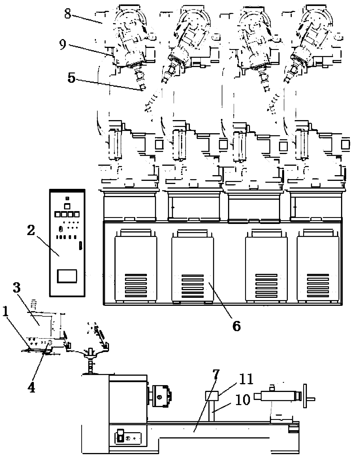
[0079] Embodiment: refer to attached Figure 1-11 , 4a, 4a 1, 4a 2, 4b, 4b 1, 4b2, 5a, 5b, as shown, the front and back welding process of the main shaft based on the welding total drive system includes the following process steps:

[0080] Front side welding

[0081] S1: Pre-spelling

[0082] Put the large flange 3 and small flange 2 on the main shaft 1 according to the requirements of the drawings, and fix them by spot welding on the non-groove side;

[0083] S2: warm up

[0084] Preheat the spot-welded spindle 1 in an oven at 230°C and keep it warm for 1 hour until the workpiece is at 150-200°C;

[0085] S3: Spindle 190 degree rotation installation

[0086] Refer to attached Figure 8 , 10 As shown, hoist the preheated main shaft 1 and armrest shaft to the welding workstation, and fix the main shaft 1 vertically through the 90-degree fixing device;

[0087] The 90-degree fixing device includes a vertical pile 11, an automatic compactor 10 fixed on the vertical pile 1...


PUM


Abstract

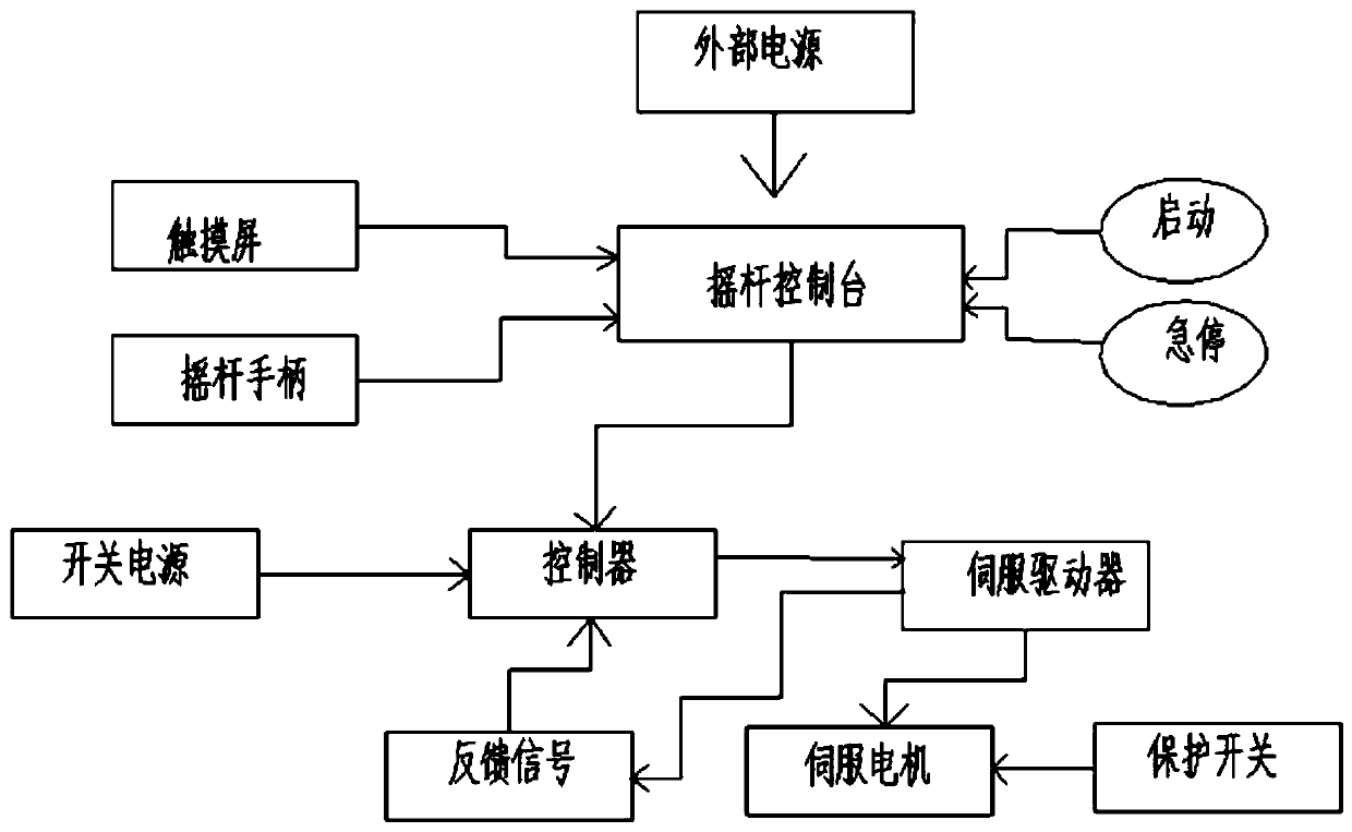
The invention discloses a main shaft front and back welding process based on a welding main driving system. The main shaft front and back welding process comprises front welding and back welding. The improvement of front welding is that existing horizontal welding is improved to be vertical welding after 90-degree rotating, wherein current welding parameters are determined on the premise of ensuring the depth of fusion under the operation mode. The improvement of back welding is that a total welding driving system is adopted, the position of a welding gun is indirectly adjusted through welding driving instead of direct manual adjustment by workers, and the risk that operators are scalded by the welding gun is eliminated. Welding point positions are adjusted by a control table, so that the precision is larger. The quality of weld seam metal is high. The performance is stable. The appearance is attractive. The production efficiency is greatly improved. The labor force and the production cost are reduced. Higher-quality products are manufactured for customers. A very high practical value is realized.

Description

technical field [0001] The invention relates to the field of welding technology, in particular to a front and back welding process of a main shaft based on a welding total drive system. Background technique [0002] The welding of the main shaft includes front welding and reverse welding, and the effect of welding is mainly based on front welding, supplemented by reverse welding. [0003] In the front welding process, the traditional shaft welding is to weld the workpiece horizontally. Since the two flanges have a groove of 18mm, but because the size of 18mm is smaller than the protective sleeve of the welding torch, the welding torch can only reach the surface of the groove, causing the welding wire to dry. The current loss of elongation welding is large, and the penetration depth cannot be guaranteed. [0004] During the welding process of the reverse side, the adjustment of the welding torch is directly adjusted manually by the worker. This manual adjustment will cause t...

Claims


Application Information

Patent Timeline
IPC IPC(8): B23K9/16B23K9/32B23K9/235
CPCB23K9/16B23K9/235B23K9/32
Inventor 李铮赵佳伟
Owner JIANGSU TONGLI MACHINERY
Learn More