
Pneumatic swirling tundish for continuous casting

A tundish and continuous casting technology, which is applied to casting equipment, casting molten material containers, manufacturing tools, etc., can solve problems such as difficult ladle long nozzle installation and replacement, complicated swirl tundish structure, and extended path, etc., and achieves favorable Floating removal, simple structure, and the effect of promoting collision growth

Inactive Publication Date: 2019-09-17
NORTHEASTERN UNIV
View PDF7 Cites 5 Cited by
  • Summary
  • Abstract
  • Description
  • Claims
  • Application Information

AI Technical Summary

Problems solved by technology

Although this method can make the molten steel spiral up in the swirl chamber, prolong the path of the molten steel in the tundish, and provide sufficient time for the inclusions to float up; the rotation of the molten steel provides centripetal force for the inclusions, and the inclusions will Move towards the center of the swirl chamber to promote the collision growth and floating removal of inclusions, but the structure of the swirl tundish is relatively complicated, and the ladle shroud outlet structure is L-shaped, which is difficult to produce and difficult to install and replace the ladle shroud

Method used


Image

  • Pneumatic swirling tundish for continuous casting
  • Pneumatic swirling tundish for continuous casting
  • Pneumatic swirling tundish for continuous casting

Examples


Embodiment

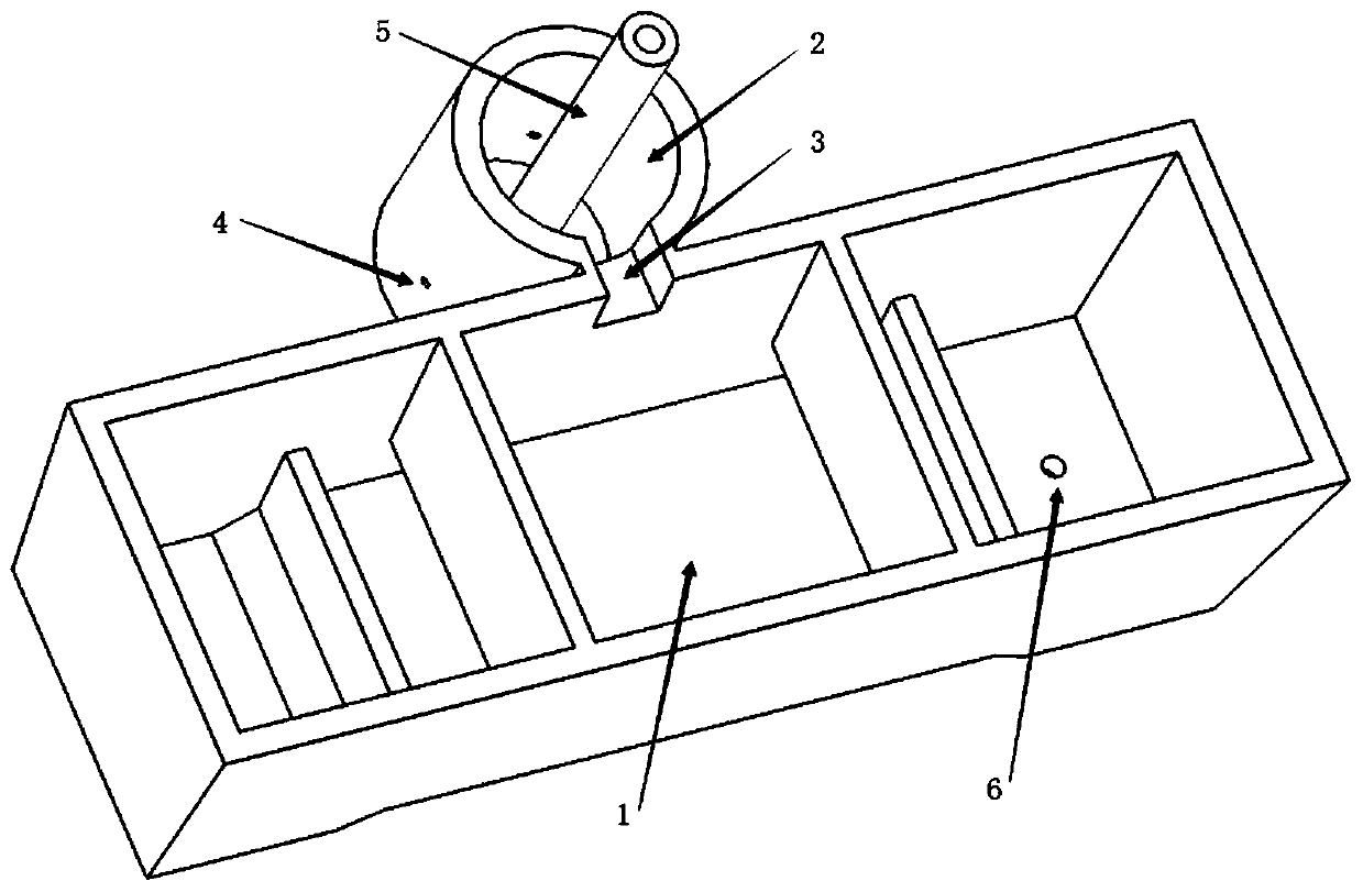
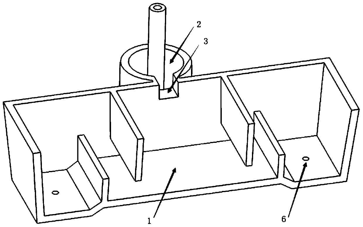
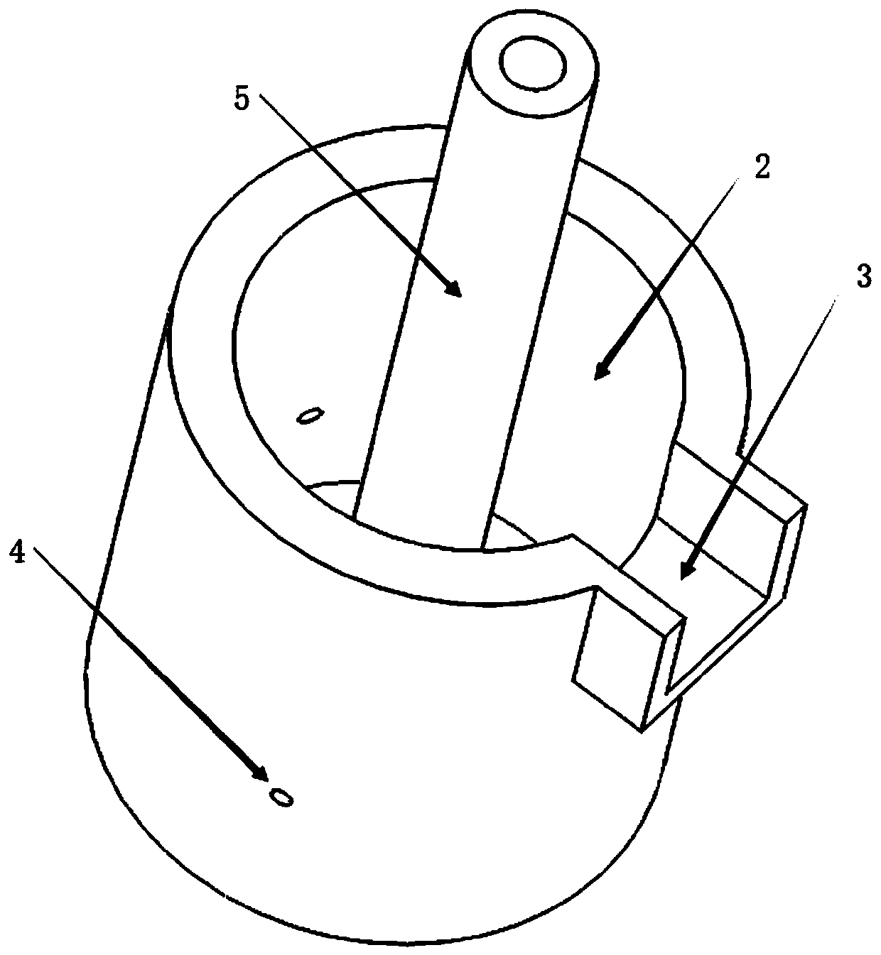
[0034] The metallurgical effect of the aerodynamic swirl tundish described in this patent is studied by using water model experiments and numerical simulations. The structure of the aerodynamic swirl tundish used for simulation research in the present invention is as follows Figure 1-3 As shown, the size parameters are as Figure 4-6 shown.

[0035] Among them, the length of the top of the tundish body 1 is L 1 =4180mm, width L 4 =1200mm, the bottom length of tundish body 1 is L 2 =3980mm, width L 3 =1000mm, height H of tundish body 1 1 =1000mm (the size shown is only the fluid area of ​​the tundish, not including the refractory part); the inner diameter of the swirl chamber 2 of the external tundish Φ 1 =700mm, outer diameter Φ 2 =900mm, height H 2 =800mm (excluding the refractory part); the length of the groove or groove 3 between the tundish body 1 and the external tundish swirl chamber 2 is L=220mm, L'=240mm, width S=250mm, height H =200mm; Aperture diameter Φ of ...


PUM


Abstract

The invention provides a pneumatic swirling tundish for continuous casting, the pneumatic swirling tundish is composed of a tundish main body and an external tundish swirling chamber; the tundish main body communicates with the external tundish swirling chamber by a trench or a groove; a plurality of inclined blowing air holes are uniformly formed in the side wall away a certain height from the bottom of the external tundish swirling chamber along the circumference, the trench or the groove is positioned in the middle position of the tundish, the center surface of the trench or the groove is coincided with the center surface of the tundish main body and the external tundish swirling chamber; and the whole pneumatic swirling tundish is symmetric in left and right sides. The pneumatic swirling tundish for the continuous casting provided by the invention has the advantages of simple structure and low cost, and can realize the rotating flow of the molten steel under the driving action of the gas, and combines the bubble impurity removing to improve the removal efficiency of inclusions in the tundish.

Description

technical field [0001] The invention belongs to the technical field of continuous casting, and in particular relates to a pneumatic swirl tundish for continuous casting. Background technique [0002] Modern iron and steel enterprises usually adopt continuous casting technology in order to improve production efficiency. In the continuous casting process, the molten steel in the tundish enters the mold through the sliding nozzle and the submerged nozzle, and the injection amount of the molten steel from the tundish to the mold and the flow of the molten steel in the mold are realized by using the stopper rod and the sliding nozzle. Behavior control is of great significance for stable operation and guarantee of slab quality. Among the many metallurgical functions of the tundish, the degree of removal of inclusions has always been the focus of metallurgists. For continuous casting of molten steel, the optimal design of the flow control device in the tundish plays an important ...

Claims


Application Information

Patent Timeline
IPC IPC(8): B22D41/00B22D1/00
CPCB22D1/005B22D41/00
Inventor 罗志国刘志远顾英杰杨伟栋邹宗树
Owner NORTHEASTERN UNIV
Learn More