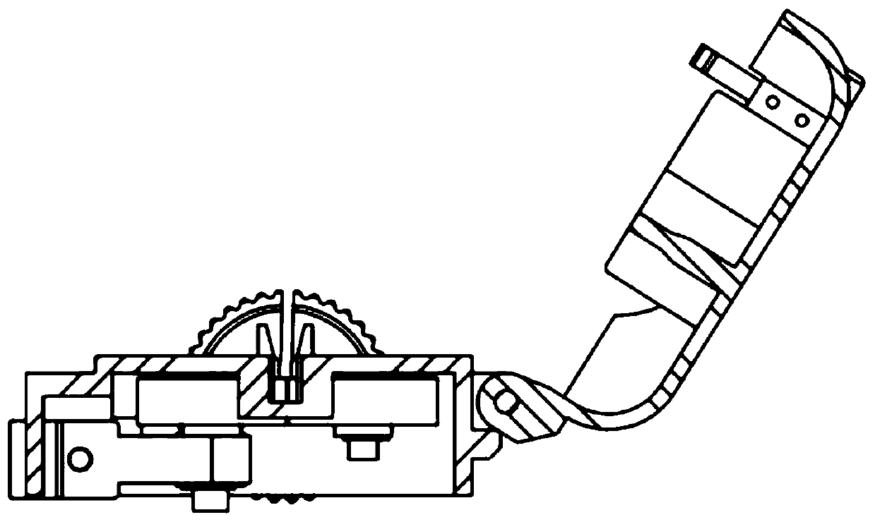
Control device of slender body instrument
A technology of control device and slender body, which is applied in the direction of surgical instrument support, surgical manipulator, surgical robot, etc., can solve the problems of oppression, long training time, complicated manual intervention operation, etc., and achieve the effect of ensuring stability and reducing injuries
- Summary
- Abstract
- Description
- Claims
- Application Information
AI Technical Summary
Problems solved by technology
Method used
Image
Examples
Embodiment 1
[0027] see Figure 1-3 , in an embodiment of the present invention, a control device for a slender body instrument, comprising:
[0028] The linear drive part 1 is used to drive the slender body instrument forward or backward;
[0029] The rotation driving part 2 is used to drive the slender body instrument to rotate axially; and
[0030] The bottom support body 3 is used to stably support the linear drive part 1 and the rotary drive part 2, and the bottom support body 3 is equipped with functional modules such as a power supply and a main control system.
[0031] Wherein, the linear drive part 1 and the rotary drive part 2 are linearly arranged and installed on the bottom support body 3 in such a way that their central axes are aligned.
Embodiment 2
[0033] see Figure 1-3 , the difference between this embodiment and embodiment 1 is:
[0034] In this embodiment, the linear driving part 1 includes a front upper cover plate, and the front upper cover plate includes two integrally formed pressing blocks, and the pressing blocks are used to cooperate with the slender instrument guide on the front housing. Groove, limit the slender body device; four integrally formed magnet embedded columns are located on the back of the front upper cover for installing magnets. The method realizes the closing and locking of the front upper cover and the front case.
[0035] In this embodiment, the rotary driving part 2 includes a rotary driving motor 7, a driving bevel gear 4, a bearing seat 6 and a driven bevel gear 9, and the driving bevel gear 4 is installed on a small bevel gear shaft 5 with a flange The bearing seat 6 of the mounting plate is installed on the bottom plate through the plate, the active bevel gear 4 and the small bevel ge...
PUM
 Abstract
Description
Claims
Application Information
 - R&D Engineer
- R&D Manager
- IP Professional
- Industry Leading Data Capabilities
- Powerful AI technology
- Patent DNA Extraction
Browse by: Latest US Patents, China's latest patents, Technical Efficacy Thesaurus, Application Domain, Technology Topic, Popular Technical Reports.
© 2024 PatSnap. All rights reserved.Legal|Privacy policy|Modern Slavery Act Transparency Statement|Sitemap|About US| Contact US: help@patsnap.com


