Particulate matter concentration detection device

A technology for particle concentration and detection device, which is applied in measurement devices, particle suspension analysis, suspension and porous material analysis, etc. It can solve the problems of dust deposition, low accuracy, and cumbersome devices, so as to overcome large background noise and reduce deposition. The probability of , the effect of reducing the contact area

Pending Publication Date: 2019-09-13
WUHAN CUBIC OPTOELECTRONICS
View PDF2 Cites 5 Cited by
  • Summary
  • Abstract
  • Description
  • Claims
  • Application Information

AI Technical Summary

Problems solved by technology

However, the disclosed particle concentration detection device includes a flow meter, which has the technical defects of bulky device, complex structure, high cost, and unfavorable batch matching use.
[0005] In order to simplify the structure of the device and reduce the cost of the device, a particle concentration detection device is disclosed in the patent document WO2018100209A, which prevents the particles in the measured air flow from depositing on the photoelectric conversion device by setting three paths of clean air to wrap the measured air flow. One path of clean air includes two paths of clean air located on both sides of the measured airflow and parallel to the measured airflow, and one path of clean air perpendicular to the measured airflow. This device has a simple structure, low cost, and is convenient for batch use. A path of clean air perpendicular to the measured air flow, which is likely to impact the measured air flow in the air flow channel, affecting the accuracy and stability of particle detection
And because the sheath flow channel and the air flow channel are located at the same height, the clean air is easy to mix with the measured air flow, and the clean air does not have an obvious isolation effect on the measured air flow and the photoelectric conversion device, which still leads to dust deposition
Dust deposition will increase the background noise of particle detection, causing misjudgment of particle detection. Therefore, the particle concentration detection device in the prior art has low accuracy and poor stability of particle detection.

Method used


Image

  • Particulate matter concentration detection device
  • Particulate matter concentration detection device
  • Particulate matter concentration detection device

Examples


Embodiment 1

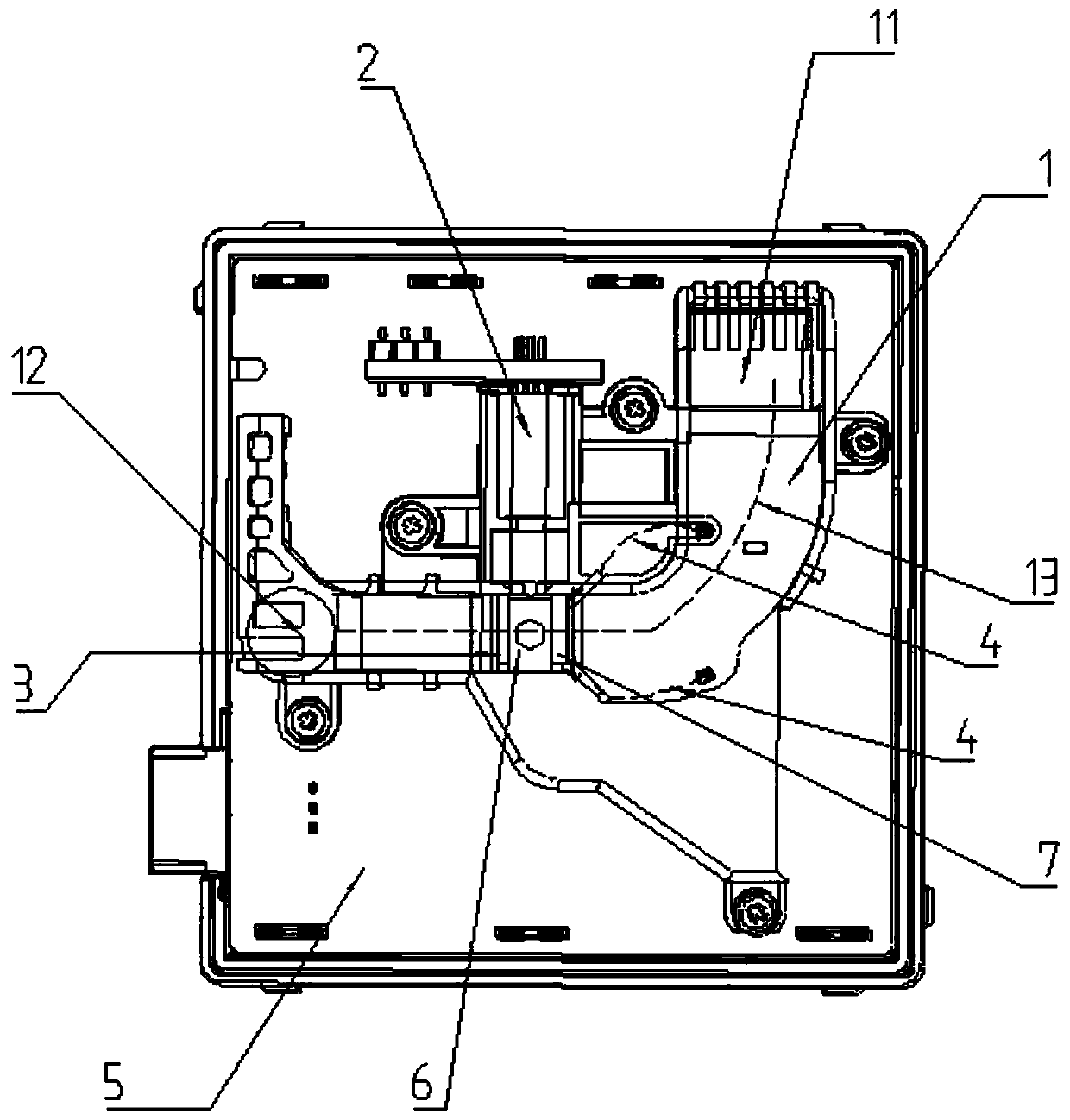
[0048] Please refer to figure 1 , the present embodiment provides a particle concentration detection device, the particle concentration detection device includes a housing 1, a laser emitting device 2, a photoelectric conversion device 3, a sheath flow channel 4, a circuit board 5, a laminar flow sheet 6 and a guide flow plate7.

[0049] The housing 1 includes an air inlet 11, an air outlet 12, and an air flow passage 13 defined by the housing 1, and the air flow passage 13 is used to guide the measured air flow from the air inlet 11 of the particle concentration detection device to the Air outlet 12.

[0050] The laser emitting device 2 is used to emit laser light to irradiate the particles in the measured air flow and generate scattered light. The laser emitting device 2 is arranged inside the housing 1 and is located on one side of the air flow channel 13. The laser emitting device 2 The laser emitting direction of the device 2 is perpendicular to the extending direction ...

Embodiment 2

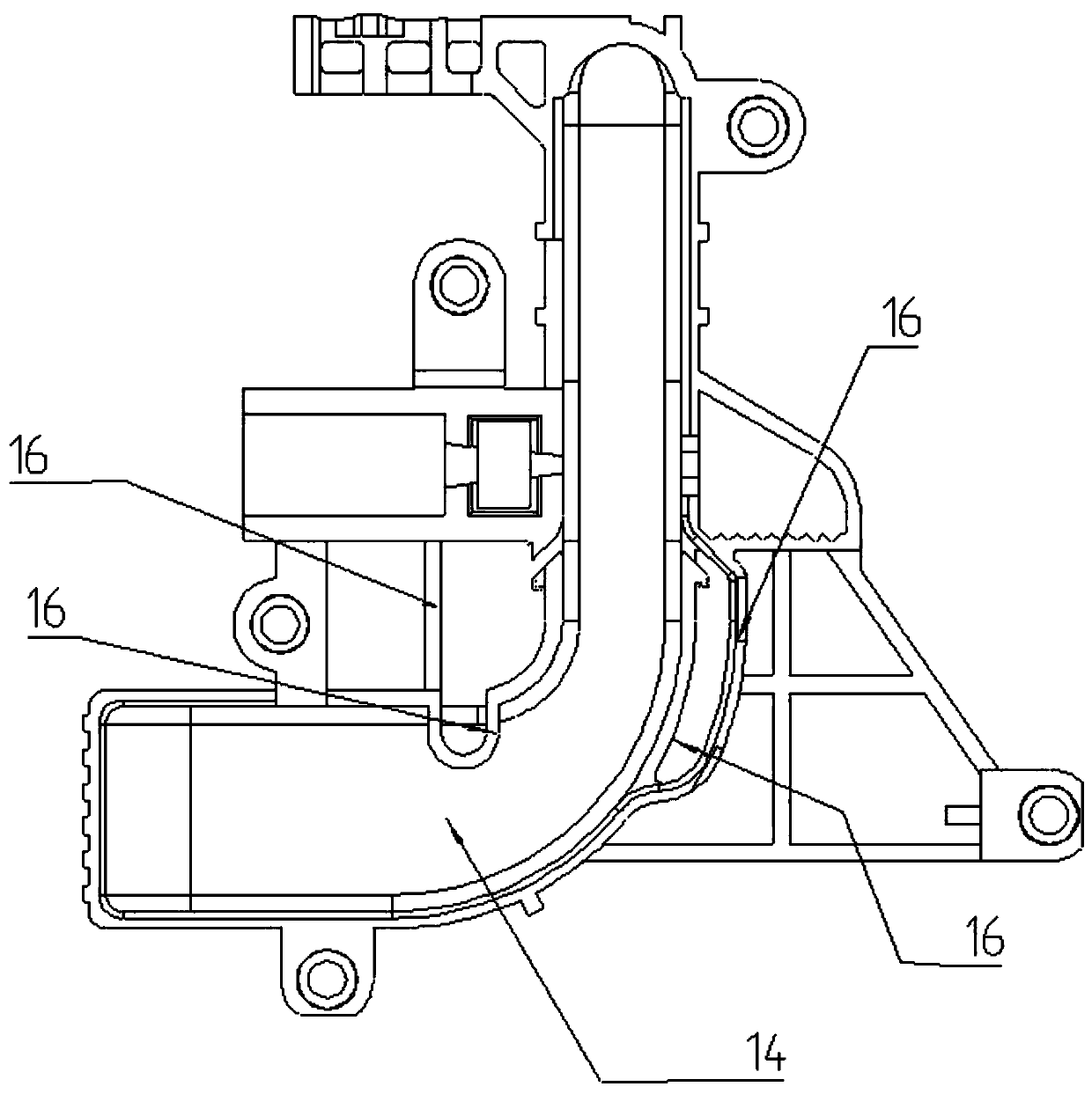
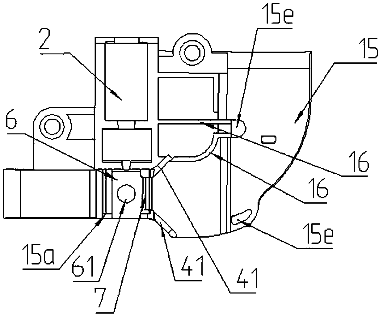
[0072] Please refer to Figure 7 with Figure 8 , this embodiment provides a particle concentration detection device, the difference between the particle concentration detection device and the particle concentration detection device disclosed in Embodiment 1 is that the structure of the deflector 7 is different.

[0073]In this embodiment, a certain distance is maintained between the deflector 7 and the laminar flow sheet 6 without communication. The deflector 7 is arranged in the air flow channel 13 and runs along the The direction of the airflow flow extends obliquely upwards toward the air intake surface 16a of the air-avoiding hole 15a, so as to guide the measured airflow to flow upwards, and then guide the measured airflow to flow from the upper side of the laminar flow sheet 6, while most of the clean air will flow from the upper side of the laminar flow sheet 6. The lower side of the laminar flow sheet 6 flows through, and the laminar flow sheet 6 realizes the function...

Embodiment 3

[0076] Please refer to Figure 9 with Figure 10 , this embodiment provides a particle concentration detection device, the difference between the particle concentration detection device and the particle concentration detection device disclosed in Embodiment 1 is that the structures of the laminar flow sheet 6 and the deflector 7 are different.

[0077] In this embodiment, a certain distance is maintained between the deflector 7 and the laminar flow sheet 6 without communication. The laminar flow sheet 6 is a spaced apart and symmetrically arranged on both sides of the avoidance hole 15b. For the laminar flow plate 6, the lighting channel is the interval in the middle of the laminar flow plate.

[0078] The deflector 7 is arranged in the air flow passage 13, and extends obliquely upward from the bottom of the lower housing 14 along the direction of the air flow to the air intake surface 16a of the avoidance hole 15a so as to guide the measured air flow upwards, and then Guide...


PUM


Abstract

The invention relates to a particulate matter concentration detection device. The device comprises an upper shell, a lower shell, an airflow channel, a laser emission device and a photoelectric conversion device. The device has the advantages that filtered clean air enters a sealed sheath flow channel through the two sides of a measuring channel, and the clean air is isolated from the measured airflow, so that the clean air is prevented from diffusing in a free space; a flow guide plate and a laminar flow sheet are arranged on a clearance area of the photoelectric conversion device of the lower shell, the clean air flows under the laminar flow sheet through the flow guide groove, the measured airflow flows above the laminar flow sheet through the flow guide plate, and the clean air forms alaminar flow (cleaning barrier) to wrap and blow the photoelectric conversion device, so that a probability that the particulate matters are deposited on the photoelectric conversion device is reduced, the technical problem that the particulate matter detection is misjudged due to the fact that the background noise caused by deposition of particulate matters in the measured airflow on the photoelectric conversion device is large is overcome, and the technical effects of improving the accuracy and stability of particulate matter concentration detection and prolonging the service life of the device are achieved.

Description

technical field [0001] The invention relates to the field of air quality detection, in particular to a particle concentration detection device. Background technique [0002] The particle concentration detection device is a device that uses the MIE scattering theory to measure the mass concentration of particles in the measured airflow. The particle concentration detection device usually includes an air flow channel for the air flow to be measured, a laser emitting device for generating laser light, and a photoelectric conversion device for sensing scattered light. The measured airflow flows in the airflow channel. When the particles in the measured airflow pass through the photosensitive area above the photoelectric conversion device, they are irradiated by laser light to generate scattered light. The photoelectric conversion device receives the scattered light and outputs an electrical signal. The output electrical signal obtains the particle concentration in the measured ...

Claims


Application Information

Patent Timeline
Patent Type & Authority Applications(China)
IPC IPC(8): G01N15/06
CPCG01N15/06G01N2015/0693
Inventor 熊友辉刘志强吴俊宋礼攀易海山李明亮
Owner WUHAN CUBIC OPTOELECTRONICS
Why Eureka
Try Eureka