Wrist force sensor of robot, and calibrating and detection method
A sensor and robot technology, applied in the sensor field, can solve the problems of many other error factors, evaluation, weak structural rigidity, etc., and achieve the effect of reducing robot load, realizing performance detection, and high accuracy
- Summary
- Abstract
- Description
- Claims
- Application Information
AI Technical Summary
Problems solved by technology
Method used
Image
Examples
Embodiment 1
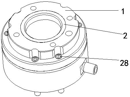
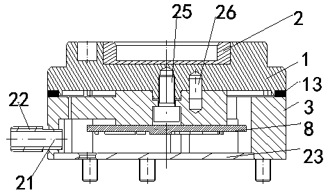
[0068] Such as Figure 1-10 As shown, a robot wrist force sensor includes an adapter ring 2, a tool end connecting flange 1, a strain sensing body 3, a strain sensitive element 7, an embedded circuit 8, a cover plate 23, and a robot tool I / O connector 22. The matching ring 2 and the tool end connecting flange 1 are used to connect the end tool of the robot. The tool end connecting flange 1 is a double-layer concentric circular platform structure with a central deep hole 9. The central deep hole 9 is matched with the adapter ring 2. The bottom of the hole 9 is distributed with a circle of counterbore 20, which is used to place the screw head of the screw 27 connected to the rigid boundary block 6 of the strain sensing body 3. The small round table is provided with a first positioning pin hole 16 and four first threaded holes 18. The first threaded hole 18 is used for the connection between the tool end connecting flange and the end tool of the robot. There is an embedded screw ...
Embodiment 2
[0070] A method for calibrating a robot wrist force sensor, comprising the following steps;
[0071] S1. Select an arbitrary ratio combination of three-directional force and three-directional moment in group M for six-axis joint loading; fix one end of the sensor to be calibrated on the base 29, and the base 29 is fixedly connected to the ground, which can be regarded as rigid Infinity, the other end of the sensor is fixedly connected with the loading head 31. The loading head 31 is a cuboid, and a space Cartesian coordinate system X, Y, Z is established above the center point of the loading head 31, the positive direction of the Z axis is downward along the origin of the coordinate system, and the force in the three directions is along the X, Y, and Z axes of the coordinate system. The three-direction force is referred to as the three-direction force in the future, and the three-direction moment is the moment along the three directions of the X, Y, and Z axes of the coordinat...
Embodiment 3
[0080] A test method for a robot wrist force sensor, comprising steps;
[0081] M1. Acquire voltage signals of group r; apply any combination of three-direction force and three-direction torque of group r in sequence, and obtain the voltage signal value of group r;
[0082] M2. Calculate the real-time calculation output results of the three-direction force and three-direction torque corresponding to the r group of voltage signals. The calculation method is:
[0083]
[0084]
[0085]
[0086]
[0087]
[0088]
[0089] Fx, Fy, Fz, Mx, My, and Mz respectively represent the output results of the three-directional force and three-directional torque, Indicates the output voltage value after loading Fx, Fy, Fz, Mx, My, Mz at the same time, represent the coefficient and function of the force in the X direction, respectively, and represent the coefficient and function of the force in the Y direction, respectively, and so on;
[0090] M3. Obtain the measurement a...
PUM
 Abstract
Description
Claims
Application Information
 - R&D
- Intellectual Property
- Life Sciences
- Materials
- Tech Scout
- Unparalleled Data Quality
- Higher Quality Content
- 60% Fewer Hallucinations
Browse by: Latest US Patents, China's latest patents, Technical Efficacy Thesaurus, Application Domain, Technology Topic, Popular Technical Reports.
© 2025 PatSnap. All rights reserved.Legal|Privacy policy|Modern Slavery Act Transparency Statement|Sitemap|About US| Contact US: help@patsnap.com


