Strip cutting machine with punching function

A tape cutting machine and punching technology, which is applied in metal processing and other directions, can solve the problem that cutting tape and punching cannot be applied, and achieve the effect of improving accuracy.

Pending Publication Date: 2019-09-10
FUJIAN QIANGKUN MACHINERY EQUIP CO LTD
View PDF4 Cites 2 Cited by
  • Summary
  • Abstract
  • Description
  • Claims
  • Application Information

AI Technical Summary

Problems solved by technology

[0006] All of the above are rolling cutting technology. Through continuous innovation and improvement, the rolling cutting technology is also constantly improving, which can be regarded as a breakthrough from one generation to the next; but in the structure of the above-mentioned tape cutting machine, the function of cutting and punching is not applicable

Method used


Image

  • Strip cutting machine with punching function
  • Strip cutting machine with punching function
  • Strip cutting machine with punching function

Examples


Embodiment 1

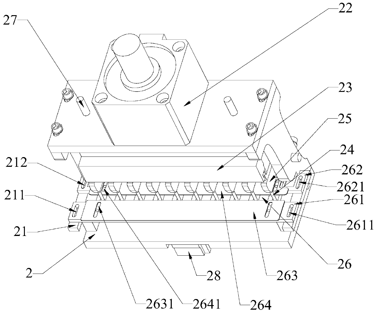
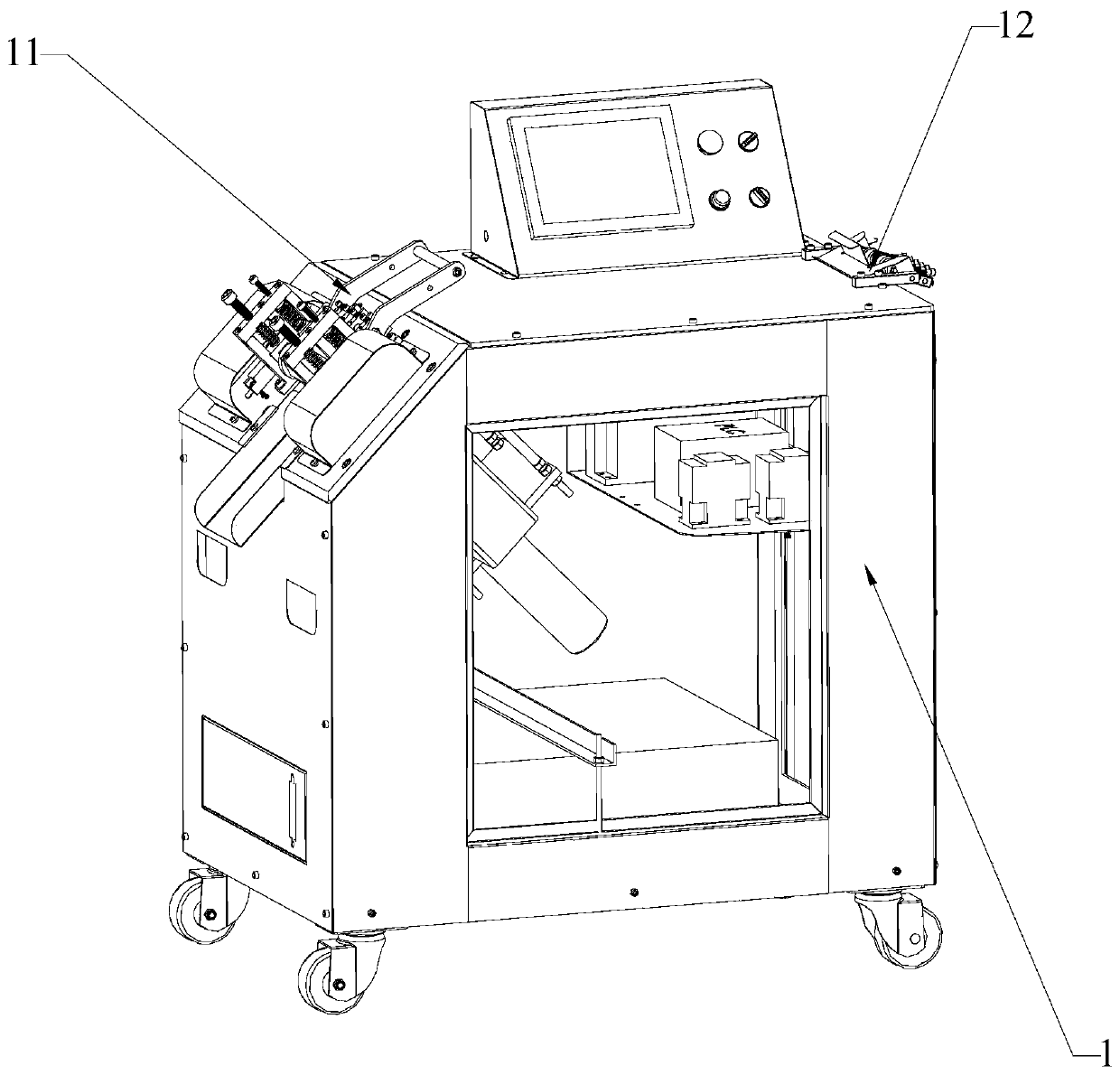
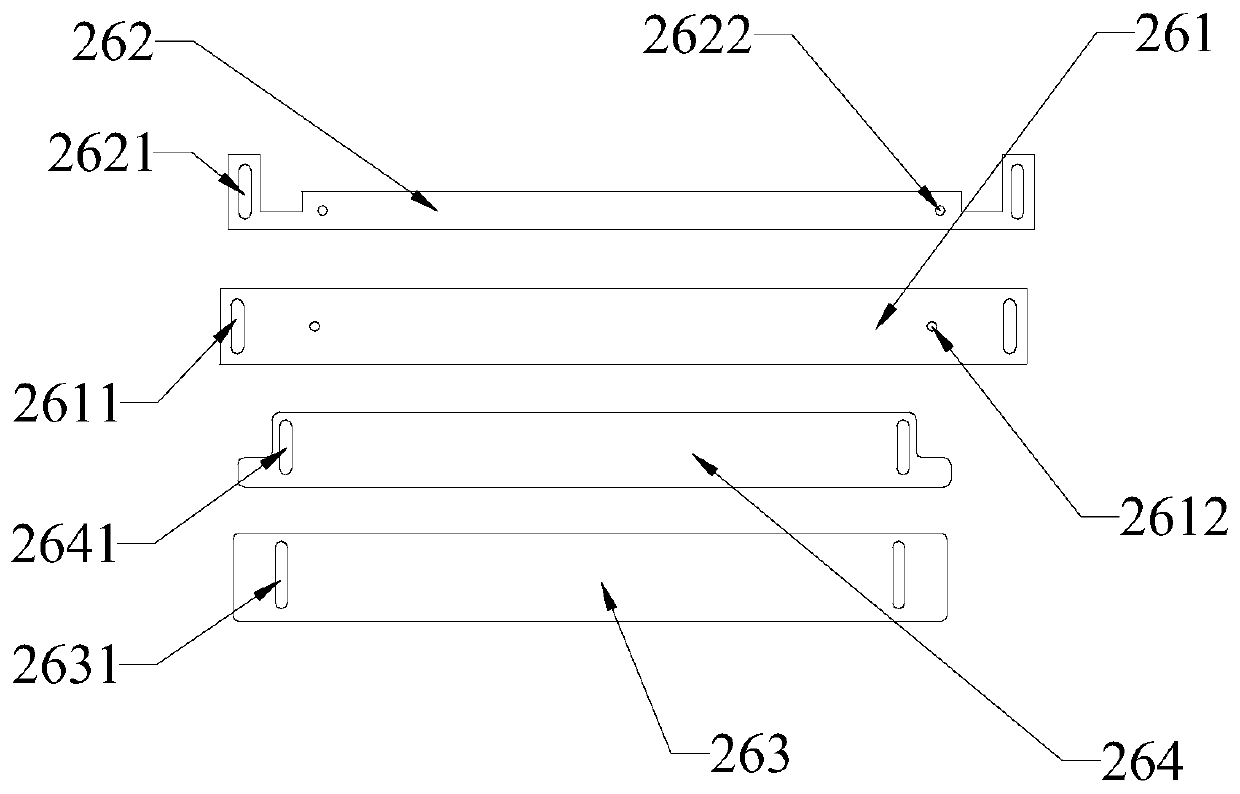
[0047] A strip cutting machine with a punching function, comprising a strip cutting machine body 1 and a punch body 2 connected to the strip cutting machine body 1; the punch body 2 includes a frame 21, a pressure cylinder 22, a punching Pressing plate 23, punching needle body 24, punching needle seat 25 and feeding channel 26; the pressure cylinder is a driving device with a piston rod, the cylinder body of the pressure cylinder 22 is connected to the frame 21, and the punching pressing plate 23 Connected to the lower end of the piston rod of the pressure cylinder 22, the lower part of the punching plate 23 is provided with a convex groove 231, and the upper end of the punching needle body 24 is provided with a convex edge 241 matching the convex groove 231. The punching needle The convex edge 241 of the body 24 is connected in the convex groove 231 of the punching platen 23, the punch seat 25 is connected to the frame 21, the punch seat 25 is provided with a vertical through ...


PUM


Abstract

The invention relates to the technical field of strip cutting machine structures, in particular to a strip cutting machine with the punching function. The strip cutting machine comprises a strip cutting machine body and a punching device body connected to the strip cutting machine body, the punching device body comprises a rack, a pressure cylinder, a punching pressing plate, a punching needle body, a punching needle base and a strip passing channel, the pressure cylinder drives the punching needle body to move in the vertical direction, the punching needle body is driven to move in the vertical direction, a strip passing through the strip passing channel is punched, the punching needle body is limited through a punching needle base, when the punching needle body vertically moves, limitingis achieved, punching accuracy is improved, the punching needle base is horizontally moved, a convex edge on the upper end of the punching needle body slides in a convex groove of the punching pressing plate, the spacing position between the punching needles can be flexibly adjusted, the punching device body is connected or movably connected to the strip cutting machine body, before the strip issubjected to rolling cutting, the strip cutting machine finishes positioning punching of various specifications.

Description

technical field [0001] The invention relates to the technical field of tape cutting machine structure, in particular to a tape cutting machine with a punching function. Background technique [0002] Tape cutting machine is a special equipment for manufacturers of clothing, shoemaking, bag making, etc. to cut accessories and materials to length. The function is also continuously improved with the market demand. In order to enhance work efficiency, rolling cutting technology in other fields is also applied to the field of tape cutting machine. This cross-industry technology application has brought more business opportunities to the tape cutting machine industry; however, Most of the existing hob cutting technology is driven by the motor to rotate the hob at a uniform speed. The patterns that need to be hob are engraved on the hob and rotated continuously at a single circle at an even speed to roll the webbing, materials, etc.; its feeding depends on the hob. The rolling of th...

Claims


Application Information

Patent Timeline
Patent Type & Authority Applications(China)
IPC IPC(8): B26F1/14B26D7/26B26D9/00
CPCB26F1/14B26D7/2628B26D9/00
Inventor 王晓美黄显林鸿乾
Owner FUJIAN QIANGKUN MACHINERY EQUIP CO LTD
Why Eureka
Try Eureka