
Single-phase current-type high-frequency chain matrix power electronic transformer topology and modulation method thereof

A high-frequency transformer and power electronics technology, applied in the direction of converting AC power input to AC power output, electrical components, output power conversion devices, etc., can solve the problems of insulating oil environmental pollution, affecting normal operation, and high no-load loss. Achieve the effects of reducing switching loss, improving efficiency, and suppressing voltage spikes

Active Publication Date: 2019-09-06
YANSHAN UNIV
View PDF4 Cites 3 Cited by
  • Summary
  • Abstract
  • Description
  • Claims
  • Application Information

AI Technical Summary

Problems solved by technology

At the same time, traditional power electronic transformers have many disadvantages: large volume, heavy weight, high no-load loss, and environmental pollution caused by the use of insulating oil; traditional distribution network transformers couple AC voltage from the primary side to the secondary side through the iron core and windings. side, in order to realize the transformation of voltage level
Since the traditional transformer does not have the ability to control the voltage and current, as long as there is any power quality problem on one side of the primary side and the secondary side, it will be transmitted to the other side, affecting the normal operation of the other side; the traditional transformer needs to be equipped with special relay protection device for protection

Method used


Image

  • Single-phase current-type high-frequency chain matrix power electronic transformer topology and modulation method thereof
  • Single-phase current-type high-frequency chain matrix power electronic transformer topology and modulation method thereof
  • Single-phase current-type high-frequency chain matrix power electronic transformer topology and modulation method thereof

Examples


Embodiment Construction

[0029] The following will clearly and completely describe the technical solutions in the embodiments of the present invention with reference to the accompanying drawings in the embodiments of the present invention. Obviously, the described embodiments are only some, not all, embodiments of the present invention. Based on the embodiments of the present invention, all other embodiments obtained by persons of ordinary skill in the art without making creative efforts belong to the protection scope of the present invention.

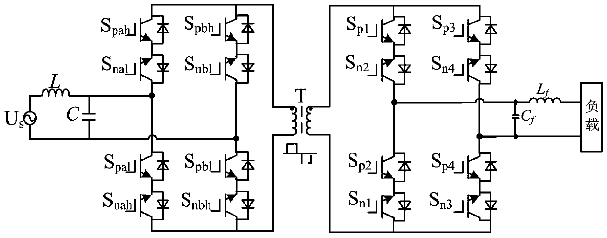
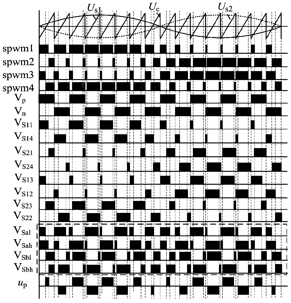
[0030] The purpose of the present invention is to provide a single-phase current-type high-frequency chain matrix power electronic transformer topology and modulation method, which can realize the output of stable AC voltage, and can also realize the output of AC voltage with variable frequency. The front stage eliminates the voltage peak on the primary side of the transformer by using the current-type integral unipolar frequency multiplication SPWM modulation ...


PUM


Abstract

The invention discloses a single-phase current-type high-frequency chain matrix power electronic transformer topology and a modulation method thereof. The topology comprises a power network, a front-stage matrix converter, a high-frequency transformer, a post-stage matrix converter, an output filter and a load which are sequentially connected. The high-frequency transformer is used for magnetic coupling and power transferring, and the conversion of an output voltage and a frequency is achieved by the current-type circuit topology. In order that a bidirectional switch of the matrix converter reasonably works, a decoupling modulation strategy of which integral monopole frequency multiplication of the transformer front-stage circuit and the post-stage circuit are discretely combined is proposed; the front stage employs an integral control mode to achieve safety conversion of the matrix converter, and a voltage peak generated by leakage inductance of the transformer is effectively prevented; and the post stage employs a discrete control mode to reduce the switch action frequency, the switch loss of the device is reduced, the system efficiency is improved, and detail mode analysis is performed on a modulation principle and a working condition of a main circuit.

Description

technical field [0001] The invention relates to the field of power electronic power converter topology and its modulation, in particular to a single-phase current-type high-frequency chain matrix power electronic transformer topology and modulation method. Background technique [0002] In the traditional power grid, the distribution network transformer plays a very important role as a device for voltage level conversion and energy transmission. Traditional power transformers have the advantages of simple structure, high reliability, and low cost. At the same time, traditional power electronic transformers have many disadvantages: large volume, heavy weight, high no-load loss, and environmental pollution caused by the use of insulating oil; traditional distribution network transformers couple AC voltage from the primary side to the secondary side through the iron core and windings. side, in order to realize the transformation of the voltage level. At the same time, the wind...

Claims


Application Information

Patent Timeline
IPC IPC(8): H02M5/293
CPCH02M5/293
Inventor 闫朝阳康鸣宋雪微赵丁选张祝新刘爽
Owner YANSHAN UNIV
Learn More