
Laser emitter and emitting method thereof

A technology of laser transmitter and laser diode, which is applied in the direction of lasers, phonon exciters, laser components, etc.

Pending Publication Date: 2019-09-06
JIANGSU TIANNING PHOTON TECH +1
View PDF8 Cites 1 Cited by
  • Summary
  • Abstract
  • Description
  • Claims
  • Application Information

AI Technical Summary

Problems solved by technology

Assuming that the ranging resolution is required to be 1cm, the corresponding laser transmission time is 67ps, and the laser pulse width of the existing technology is several ns, which is two orders of magnitude different.

Method used


Image

  • Laser emitter and emitting method thereof
  • Laser emitter and emitting method thereof
  • Laser emitter and emitting method thereof

Examples


Embodiment Construction

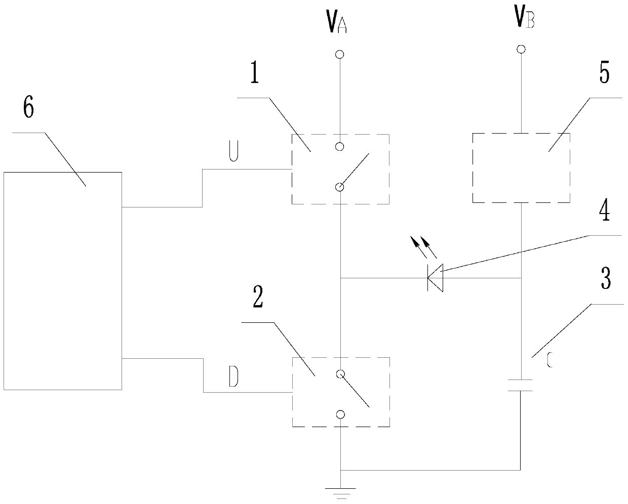
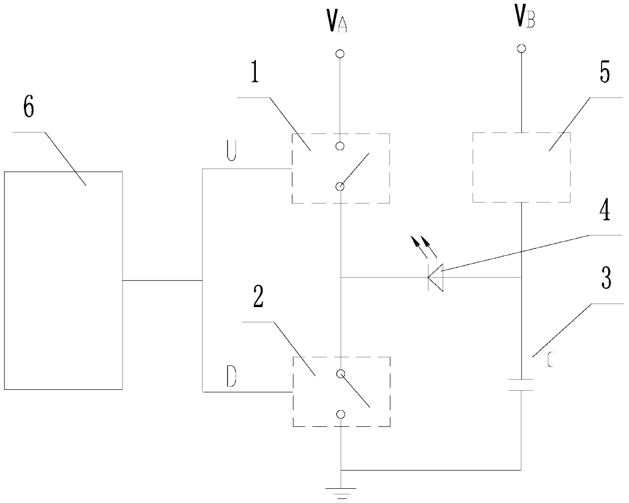
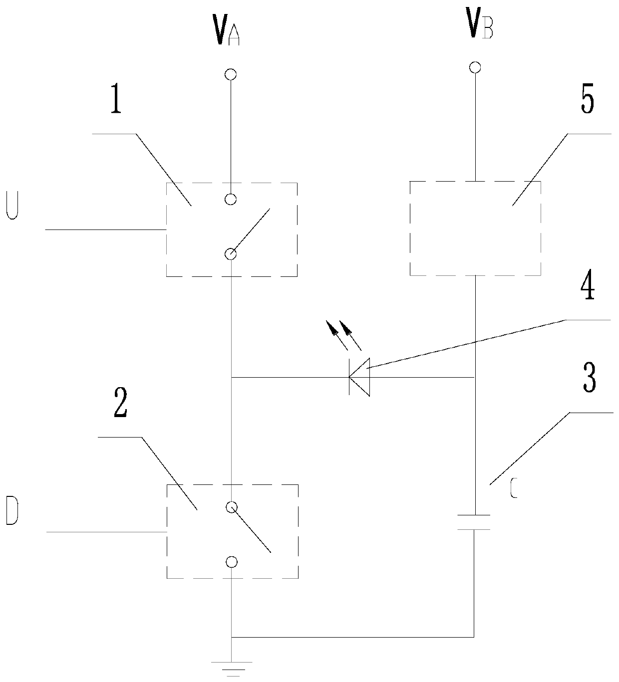
[0030] The present invention as Figure 1-4 As shown, a laser transmitter includes a semiconductor laser diode 4, a first electronic switch 1, a second electronic switch 2, an energy storage capacitor 3, a bias circuit 5 and a switch driver 6;

[0031] The high end of the first electronic switch 1 is connected to the DC regulated power supply V A connected, the low end of the first electronic switch 1 is connected to the high end of the second electronic switch 2; the low end of the second electronic switch 2 is grounded;

[0032] The high end of the bias circuit 5 is connected to the DC regulated power supply V B connected, the low end of the bias circuit 5 is connected to the high end of the energy storage capacitor 3, and the low end of the energy storage capacitor 3 is grounded;

[0033] The anode of the semiconductor laser diode 4 is connected between the bias circuit 5 and the energy storage capacitor 3;

[0034] The cathode of the semiconductor laser diode 4 is conne...


PUM


Abstract

The invention relates to a laser emitter and an emitting method thereof, in particular to a laser emitter for emitting high-power, high-frequency and sub-nanosecond pulse laser light, and a laser emission method thereof. The invention provides a laser emitter of a high-power high-frequency high-precision laser ranging sensor and an emitting method of the laser emitter, and particularly provides alaser emitter capable of emitting sub-nanosecond laser pulses and a method for emitting the sub-nanosecond laser pulses by the laser emitter. The high end of a first electronic switch is connected with a direct-current voltage-stabilizing power supply, and the low end of the first electronic switch is connected with the high end of a second electronic switch; and the low end of the second electronic switch is grounded.

Description

technical field [0001] The invention relates to a laser emitter and a laser emitting method thereof, in particular to a laser emitter capable of emitting high-power, high-frequency, sub-nanosecond pulse laser and a laser emitting method thereof. Background technique [0002] With the advent of the era of artificial intelligence, laser ranging sensors are widely used in mobile robots and automotive intelligent driving lidar. However, most laser ranging sensors currently on the market are mid-to-low-end products, which cannot meet the requirements of a new generation of high-speed mobile robots and intelligent driving solid-state lidars for long distances, high frequencies, and high precision. [0003] Most of the existing laser ranging sensors use the phase ranging method. Although the accuracy is high, the ranging frequency is not high and the measuring distance is not far. Laser sensors using pulse ranging technology can increase the transmission power (increase the measur...

Claims


Application Information

Patent Timeline
Patent Type & Authority Applications(China)
IPC IPC(8): H01S5/042G01S7/481G01S17/10
CPCH01S5/0428G01S7/4814G01S17/10F41G1/473F41G11/00
Inventor 郁麒麟
Owner JIANGSU TIANNING PHOTON TECH
Learn More