
Transformer core manufacturing equipment

A technology for manufacturing equipment and transformers, applied in the direction of inductance/transformer/magnet manufacturing, magnetic core manufacturing, chemical instruments and methods, etc., can solve the problems of reduction and inconvenience, achieve simple maintenance process, save costs, and reduce manual steps The effect of the process of operation

Inactive Publication Date: 2019-09-06
ANHUI HUATENG AGRI TECH CO LTD
View PDF4 Cites 5 Cited by
  • Summary
  • Abstract
  • Description
  • Claims
  • Application Information

AI Technical Summary

Problems solved by technology

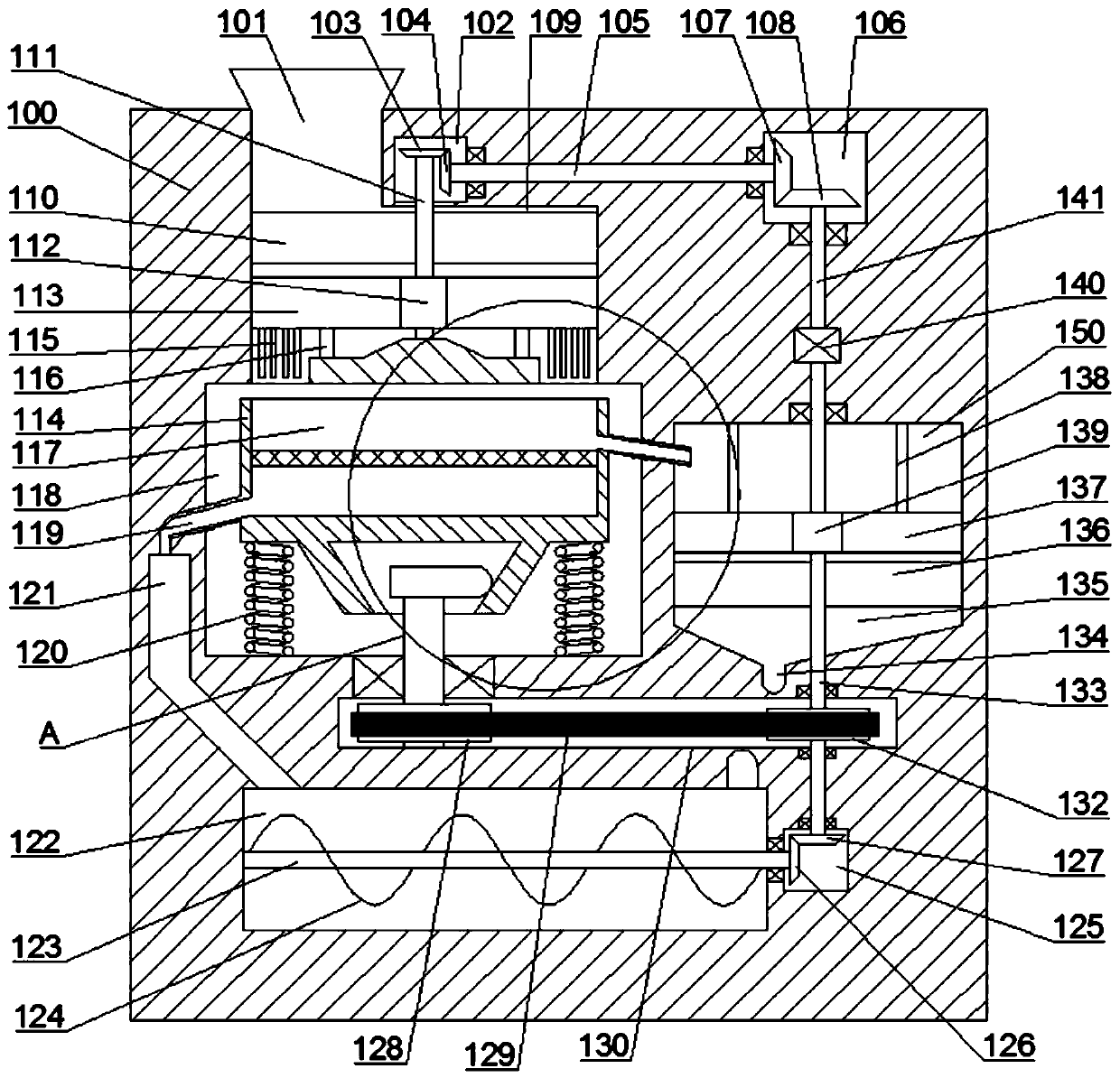
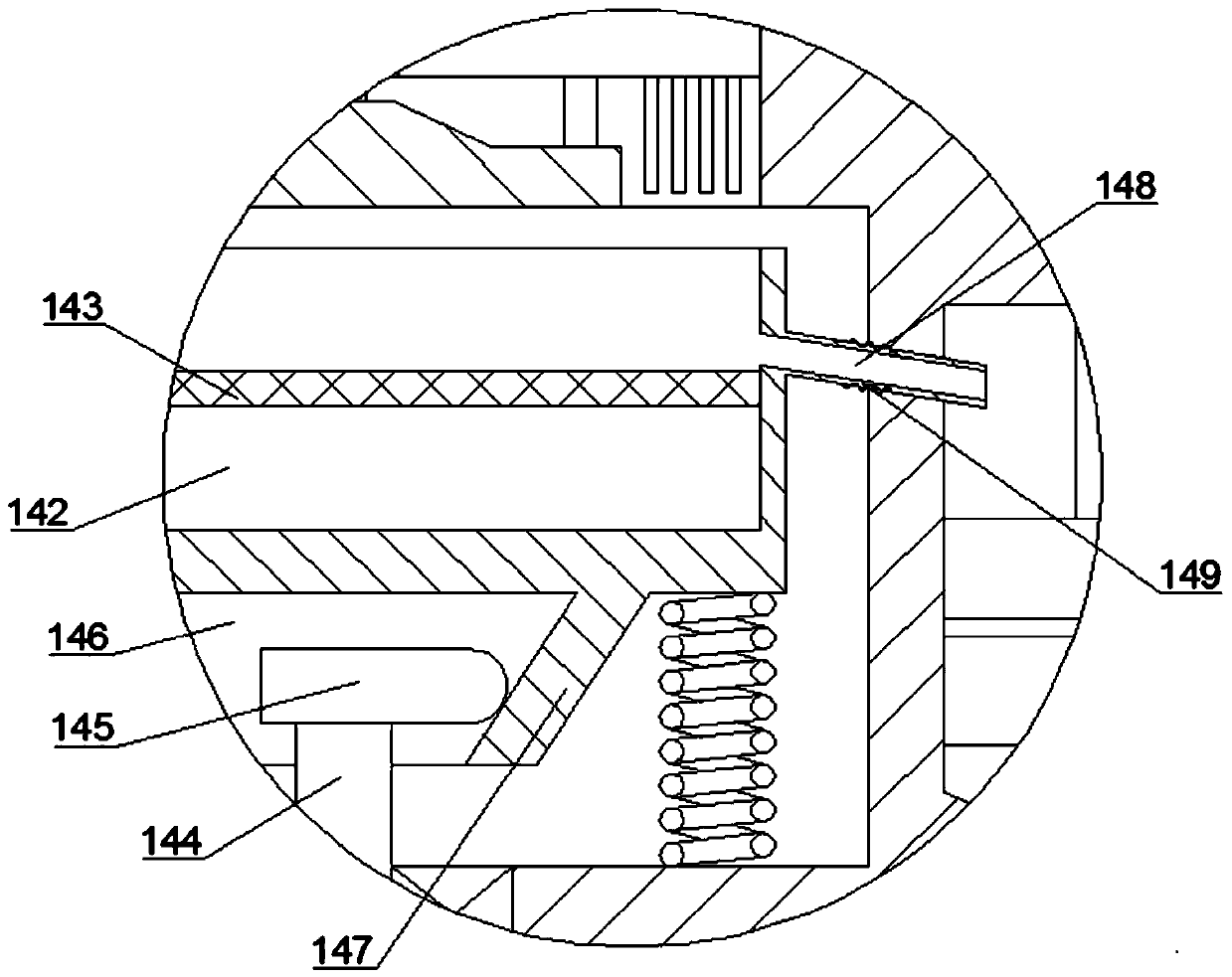
[0003] At present, the traditional production method of microcrystalline iron core is mainly carried out in steps. First, it is ground, and then the ground particle powder is mixed with a salt solution. This step-by-step process requires multiple operators to operate. It is very inconvenient, so the present invention designs a transformer magnetic core manufacturing equipment with a high degree of integration. Compared with the traditional grinding and mixing processes that are produced separately, this equipment realizes the concentration of various processes in one equipment, which improves the integration degree, reducing the process of manual step-by-step operation, saving manpower and cost

Method used


Image

  • Transformer core manufacturing equipment
  • Transformer core manufacturing equipment

Examples


Embodiment Construction

[0022] All features disclosed in this specification, or steps in all methods or processes disclosed, may be combined in any manner, except for mutually exclusive features and / or steps.

[0023]Any feature disclosed in this specification (including any appended claims, abstract and drawings), unless expressly stated otherwise, may be replaced by alternative features which are equivalent or serve a similar purpose. That is, unless expressly stated otherwise, each feature is one example only of a series of equivalent or similar features.

[0024] Below will be combined with the appended in the embodiment of the present invention Figure 1 to Figure 2 The technical solutions in the embodiments of the present invention are clearly and completely described. Obviously, the described embodiments are only some of the embodiments of the present invention, not all of them. Based on the embodiments of the present invention, all other embodiments obtained by persons of ordinary skill in t...


PUM


Abstract

The invention provides transformer core manufacturing equipment, comprising a main machine body, wherein a feeding hole extending downward is formed in the end surface of the top of the main machine body, a primary stirring cavity is formed in the bottom wall of the feeding hole in a communication manner, a primary grinding mechanism is arranged in the primary stirring cavity, a left side cavity is formed in the main machine body at the top of the primary stirring cavity, a right side cavity is formed in the main machine body at the right side of the left side cavity, a vibrating screen cavityis formed in the main machine body at the bottom of the primary stirring cavity, a vibrating screen mechanism is arranged in the vibrating screen cavity, and a belt pulley cavity is formed in the main machine body at the bottom of the vibrating screen cavity, thus the invention designs the transformer core manufacturing equipment high in integration level. Compared with the traditional way that grinding and mixing processes are separate during manufacturing, the equipment provided by the invention realizes the effect that all the processes are integrated in one equipment, the integration level is improved, a manual step-by-step operation flow is shortened, and both manpower and cost are saved.

Description

technical field [0001] The invention relates to the technical field of microcrystalline iron core manufacturing, in particular to a transformer magnetic core manufacturing equipment. Background technique [0002] Transformers are one of the most commonly used electrical appliances in the field of electric power. The iron cores of cast transformers are generally divided into two types, one is silicon steel core, the other is microcrystalline iron core, and the production of microcrystalline iron core is generally the required The solid particle powder is mixed with the solution, then dried to evaporate water, and then heated and solidified. [0003] At present, the traditional production method of microcrystalline iron core is mainly carried out in steps. First, it is ground, and then the ground particle powder is mixed with a salt solution. This step-by-step process requires multiple operators to operate. It is very inconvenient, so the present invention designs a transform...

Claims


Application Information

Patent Timeline
Patent Type & Authority Applications(China)
IPC IPC(8): H01F41/02B02C7/08B02C7/16B02C23/08B07B1/42B01F13/10
CPCH01F41/0206B02C7/08B02C7/16B02C23/08B07B1/42B01F33/831B01F33/83613
Inventor 不公告发明人
Owner ANHUI HUATENG AGRI TECH CO LTD
Learn More