
A fiber optic acoustic emission vibration sensor and partial discharge sensing system

A partial discharge and sensing system technology, applied in the field of optical fibers, can solve the problems of poor anti-interference, inability to be practical in large quantities, easily affected by the monitoring environment, etc., and achieve the effects of enhanced sensing sensitivity and simple production process.

Active Publication Date: 2021-07-20
SHANGHAI MUNICIPAL ELECTRIC POWER CO +1
View PDF9 Cites 0 Cited by
  • Summary
  • Abstract
  • Description
  • Claims
  • Application Information

AI Technical Summary

Problems solved by technology

Among them, the pulse current method is applied to the factory test of cables, so this method has high sensitivity in the laboratory environment, but it will also be affected by external noise, so the anti-interference is relatively poor, and it cannot be used in large quantities.
The high-frequency electromagnetic wave detection method can only detect at fixed points and is easily affected by the monitoring environment
Acoustic emission detection usually uses piezoelectric ceramic transducers for detection, requires remote power supply, and is susceptible to electromagnetic interference

Method used


Image

  • A fiber optic acoustic emission vibration sensor and partial discharge sensing system
  • A fiber optic acoustic emission vibration sensor and partial discharge sensing system
  • A fiber optic acoustic emission vibration sensor and partial discharge sensing system

Examples


Embodiment Construction

[0019] The present invention will be further described below through specific embodiments in conjunction with the accompanying drawings. These embodiments are only used to illustrate the present invention, and are not intended to limit the protection scope of the present invention.

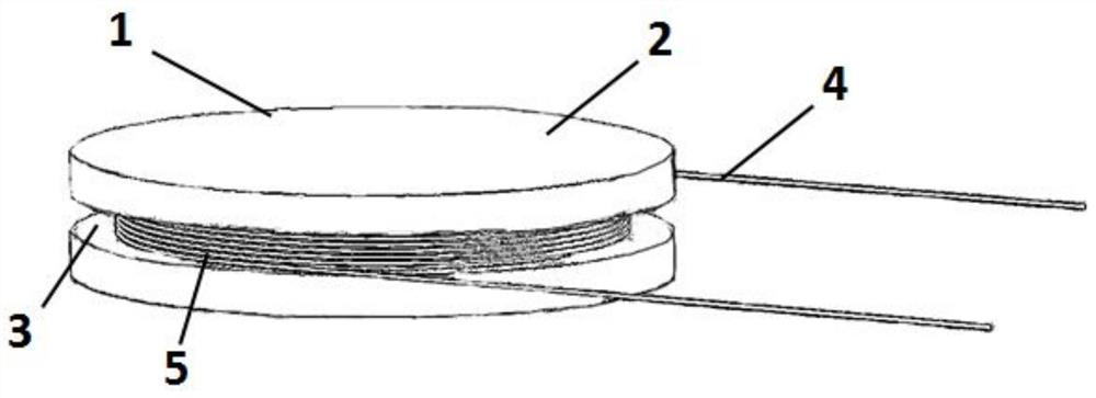
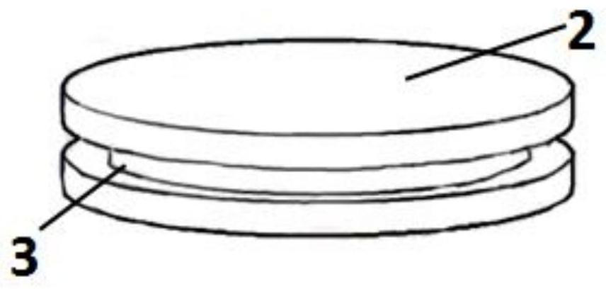
[0020] Such as figure 1 Shown, the present invention is a kind of optical fiber acoustic emission vibration sensor 1, comprises figure 2 In the cylindrical sensor head 2, the side wall of the sensor head 2 is provided with an annular groove 3 along its circumference, and the annular groove 3 is wound with a multi-turn sensing optical fiber 4, and the multi-turn sensing optical fiber 4 is covered with silicon Rubber 5 and silicone rubber 5 are covered on the sensing optical fiber 4 after natural curing of liquid silicone rubber. The Poisson's ratio of the silicone rubber 5 material is 0.49, and the expansion of its lateral dimension will also increase accordingly. The sensing fiber 4 will also ex...


PUM

PropertyMeasurementUnit
thicknessaaaaaaaaaa
thicknessaaaaaaaaaa

Abstract

The invention discloses an optical fiber acoustic emission vibration sensor, which comprises a cylindrical sensor head, an annular groove on the side wall of the sensor head along the circumferential direction of the sensor head, a multi-turn sensing optical fiber wound on the annular groove, and a multi-turn sensing optical fiber. Covered with silicone rubber. The invention has a simple manufacturing process, adopts 3D printing cylindrical silicone rubber elastic body, and winds the sensing optical fiber around the elastic body to realize the sensing head with enhanced sensitivity to backscattered light phase modulation, based on optical time domain reflection time division multiplexing technology , combined with the 3D printing sensor head, can realize the real-time, online, remote positioning and network monitoring of the partial discharge acoustic emission parameters that reflect the early fault characteristics of the power cable.

Description

technical field [0001] The invention relates to the field of optical fiber technology, in particular to an optical fiber acoustic emission vibration sensor and a partial discharge sensing system. Background technique [0002] With the rapid development of the national economy and the continuous improvement of the national grid cable voltage level, the requirements for safe and stable operation of power cables are becoming more and more important. As far as the high-voltage power cable is concerned, its production process has strict industry standards and the process is mature. Therefore, the high-voltage power cable body is almost free of partial discharge events, and for complicated cable accessories, such as cable terminals and cable intermediate joints , not only limited by the insufficient current production level, but also uncontrollable factors during on-site installation. It operates in a high-voltage environment, and there may be partial discharge caused by weak insu...

Claims


Application Information

Patent Timeline
Patent Type & Authority Patents(China)
IPC IPC(8): G01R31/12B33Y30/00
CPCB33Y30/00G01R31/1209G01R31/1218G01R31/1227G01R31/1272
Inventor 邵宇鹰庞拂飞陈真钱天宇王廷云彭鹏刘奂奂罗潇王海峰沈诗
Owner SHANGHAI MUNICIPAL ELECTRIC POWER CO
Learn More