Stress detection probe clamp

A technology of stress detection and probe clips, which is applied in the field of ultrasonic stress instruments, can solve the problems of high production cost, low measurement efficiency, and high cost, and achieve the effects of low difficulty in processing and assembly, high detection accuracy, and low production cost

Pending Publication Date: 2019-09-06
杭州戬威科技有限公司
View PDF0 Cites 2 Cited by
  • Summary
  • Abstract
  • Description
  • Claims
  • Application Information

AI Technical Summary

Problems solved by technology

There is an inherent relationship between ultrasonic velocity and stress in the measured object, and this relationship has good linearity at the same temperature. The current stress detection methods include: blind hole method, X-ray method, magnetic method and ultrasonic method. Among them, the blind hole method needs to be drilled and pasted with strain gauges before measurement. The pasting needs to meet certain process requirements, which will cause damage to the components and the operation is cumbersome. The X-ray method is non-destructive, accurate and reliable, but it can only measure micron-level thickness.
Operation needs to pay attention to ionizing radiation, high cost, low measurement efficiency, magnetic measurement method is simple to operate, fast measurement, low accuracy, ultrasonic method measurement efficiency is high and non-destructive, easy and safe to operate, with the development of modern hardware chips, accuracy and resolution The efficiency has been greatly improved. However, the detection tool is complicated to operate and the production cost is high when measuring the existing strain gauge, and it cannot be applied to various shapes of material surfaces, and the measurement effect is not good.

Method used


Image

  • Stress detection probe clamp
  • Stress detection probe clamp
  • Stress detection probe clamp

Examples


Embodiment Construction

[0021] The following are specific embodiments of the present invention and in conjunction with the accompanying drawings, the technical solutions of the present invention are further described, but the present invention is not limited to these embodiments.

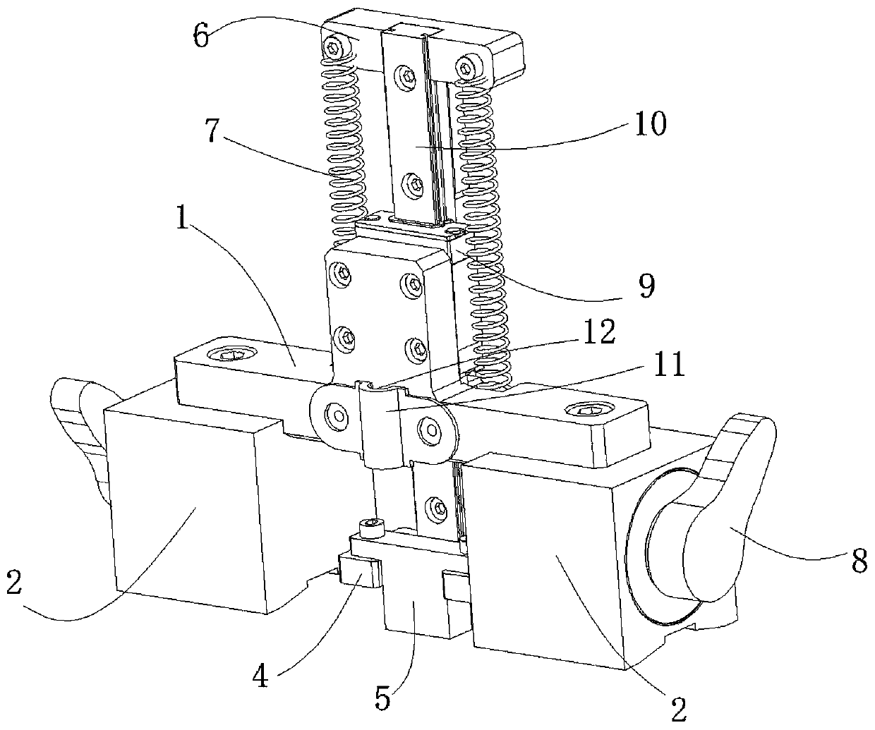
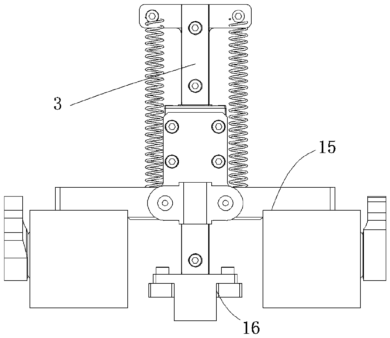
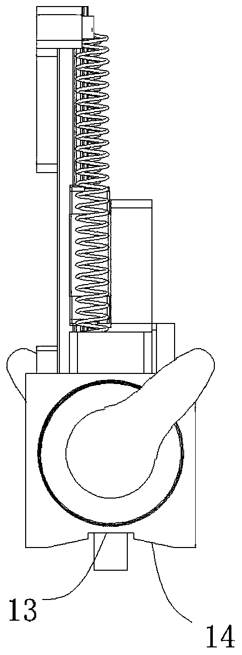
[0022] Such as Figure 1-3 As shown, the stress detection probe fixture includes a mounting base 1, a fixed base 2 and a sliding bracket 3, the mounting base 1 is fixedly connected to the fixed base 2, the mounting base 1 is slidably connected to the sliding bracket 3, and the mounting base 1 can be moved along the length of the sliding bracket 3 direction to reciprocate, the sliding bracket 3 is provided with a probe 5 and a tension spring 7, and the two ends of the tension spring 7 are respectively connected with the sliding bracket 3 and the mounting seat 1. When the tension spring 7 is in a free state, the bottom surface of the probe 5 exceeds the fixed The bottom surface of the base 2, the fixed base 2 is used to fix ...


PUM


Abstract

The invention provides a stress detection probe clamp, belongs to the technical field of ultrasonic stress gauges, and aims at solving the problems that the detection tools are complicated to operateand the production cost is high when the existing stress gauges are used for measuring measured materials. A surgical protection curtain for ultrasonic detection comprises a mounting seat, a fixed base and a sliding bracket, wherein the mounting seat is fixedly connected with the fixed base and glidingly connected with the sliding bracket; the mounting seat is capable of reciprocating along the length direction of the sliding bracket; a probe and a tension spring are arranged on the sliding bracket; two ends of the tension spring are respectively connected with the sliding bracket and the mounting seat; when the tension spring is located in a free state, the bottom surface of the probe exceeds the bottom surface of the fixed base; and the fixed base is used for fixing the stress detectionprobe clamp on the surface of a material. The stress detection probe clamp has the advantages of being convenient to use, simple in structure, low in processing and assembling difficulty, low in production cost and high in detection precision.

Description

technical field [0001] The invention belongs to the technical field of ultrasonic stress instruments, in particular to a stress detection probe fixture. Background technique [0002] When a material cannot be displaced under the action of an external force, its geometry and size will change. This deformation is called strain. When the material is deformed, a reaction force of equal size but opposite direction is generated inside to resist the external force. This reaction force per unit area is defined as stress, or when the object is deformed due to external factors, the internal force that interacts between the various parts of the object , to resist the effect of this external cause, and try to make the object return from the deformed position to the pre-deformed position. [0003] The stress measurement method based on ultrasonic acoustoelasticity theory utilizes the principle of acoustic birefringence in stressed materials. There is an inherent relationship between ul...

Claims


Application Information

Patent Timeline
Patent Type & Authority Applications(China)
IPC IPC(8): G01L1/25G01L1/26
CPCG01L1/255G01L1/26
Inventor 方文平刘日明
Owner 杭州戬威科技有限公司
Why Eureka
Try Eureka