
Temperature regulating storage device

A storage device and temperature adjustment technology, which is applied to household refrigeration devices, cooling fluid circulation devices, lighting and heating equipment, etc., can solve problems such as uneven temperature adjustment, large air-conditioning wind, and poor workability, so as to improve uneven temperature adjustment Uniformity, suppression of reduction in temperature regulation performance, and improvement of workability

Inactive Publication Date: 2019-09-03
DENSO CORP
View PDF16 Cites 0 Cited by
  • Summary
  • Abstract
  • Description
  • Claims
  • Application Information

AI Technical Summary

Problems solved by technology

[0006] In the temperature-adjusted storage device of Patent Document 1, there is a limit to evenly ventilating the entire storage with air-conditioning air, and further improvement of uneven temperature regulation is required.
In addition, if the amount of storage is small, the upper gap of the storage cannot be sufficiently closed by the damper, and there is a problem that air-conditioning air leaks from the upper gap to ventilate.
In addition, if the gap between the stored objects is large when the stored objects are arranged, there is a problem that the amount of air-conditioning air that does not contribute to the temperature adjustment of the stored objects leaks from the gap increases.
That is, in the temperature-regulated storage device of Patent Document 1, the temperature-regulated performance tends to decrease due to the amount or arrangement of the contents, and since the contents must be stored in consideration of these contents, workability is deteriorated.
In addition, the operation of disposing the damper is required in the storage operation of the stored objects, so the workability is also poor in this respect.

Method used


Image

  • Temperature regulating storage device
  • Temperature regulating storage device
  • Temperature regulating storage device

Examples


no. 1 approach

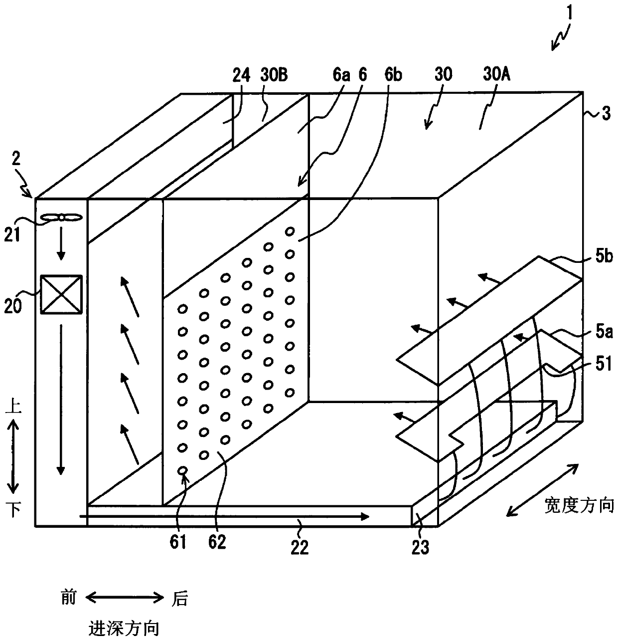
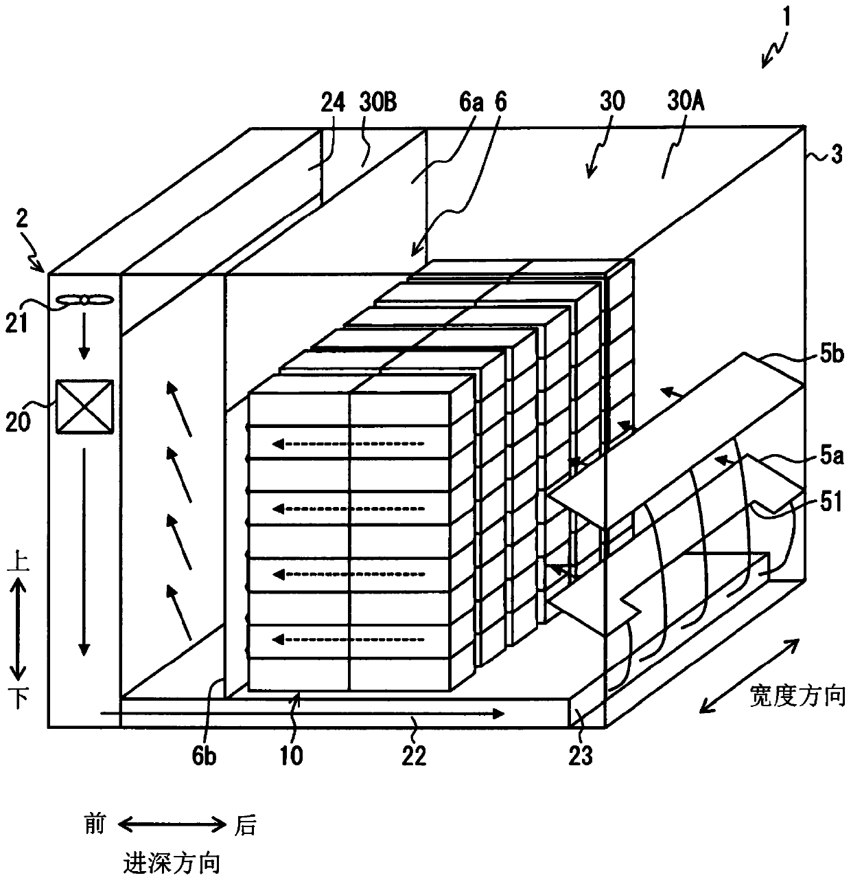
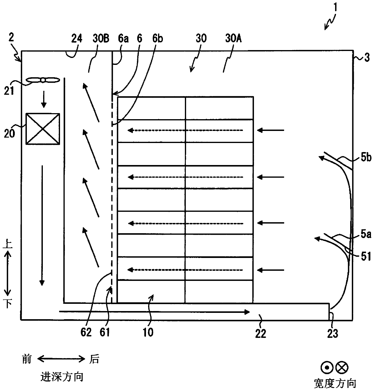
[0020] The disclosed temperature-regulated storage device is, for example, a device capable of transporting a temperature-regulated object stored in a storage room in a frozen state or a refrigerated state. The temperature-adjusted storage device is mounted on a mobile body such as a vehicle, a ship, or an aircraft, and is transported. At the time of this transportation, the temperature-regulated storage device is mounted as a container for transportation. The objects to be transported are fresh foods such as vegetables, fruits, and meat, various frozen foods that are transported in a frozen state, and the like. In addition, the object to be tempered may not be food, but may be a living thing or article that needs to be transported at a predetermined temperature.

[0021] In the first embodiment, regarding the temperature-regulated storage device 1 capable of regulating the temperature of the temperature-regulated object 10 housed in the container 3 for transportation to a pr...

no. 2 approach

[0052] refer to Figure 5 A second embodiment will be described. In the second embodiment, the same symbols as those in the drawings of the first embodiment and unexplained structures are the same as those of the first embodiment, and have the same operation and effect. In the second embodiment, only the parts different from the first embodiment will be described.

[0053] In the temperature-regulated storage device 1 according to the second embodiment, an air passage is formed in which the blowing duct 222 extends in the vertical direction at the front of the container 3 and further extends in the depth direction at the ceiling of the container 3 . The air outlet 23 is located at the upper end of the other end in the depth direction in the ventilation space 30 . That is, the air outlet 23 opens at the rear upper end in the ventilation space 30 . The suction port 24 is located at the lower end of the front part in the storage compartment 30A. That is, the conditioned air i...

no. 3 approach

[0057] refer to Image 6 A third embodiment will be described. In the third embodiment, the same symbols as those in the drawings of the first embodiment and unexplained structures are the same as those of the first embodiment, and have the same operation and effect. In the third embodiment, only the parts different from the first embodiment will be described.

[0058] In the temperature-regulated storage device 1 of the third embodiment, an air passage in which the air-sending duct 222 extends in the depth direction on the ceiling portion of the container 3 is formed. The air outlet 23 is located at the upper end of the other end in the depth direction in the ventilation space 30, similarly to the temperature-regulated storage device of the second embodiment. That is, the air outlet 23 opens at the rear upper end in the ventilation space 30 . The suction port 24 is located at the upper end of the front portion in the differential pressure forming chamber 30B. Therefore, t...


PUM


Abstract

A temperature regulating storage device (1) comprising a container (3), and an air conditioner (2) provided integrally with the container (3). A ventilation space (30) through which air-conditioned air blown from the air conditioner (2) passes between being blown out from an outlet (23) and taken in by an inlet (24) is formed inside the container (3). The temperature regulating storage device (1)further comprises a partitioning plate (6) that partitions the ventilation space (30) into a storage chamber (30A) in which an item (10) for temperature regulation is stored and a pressure differential formation chamber (30B). The partitioning plate (6) partitions the ventilation space (30) so as to form the pressure differential formation chamber (30B) between the storage chamber (30A) and the inlet (24). The partitioning plate (6) has an airflow shielding portion (6a) that blocks the air-conditioned air from the ceiling portion of the container (3) to a prescribed height, and a flow straightener portion (6b) that is formed under the airflow shielding portion (6a) and by which the air-conditioned air can pass from the storage chamber (30A) to the pressure differential formation chamber (30B) while being subjected to ventilation resistance.

Description

[0001] Cross-reference of related applications [0002] This application is based on Japanese Patent Application No. 2017-009563 filed on January 23, 2017, and the disclosure thereof is incorporated into this application by reference. technical field [0003] The present invention relates to a temperature-regulated storage device for accommodating a temperature-regulated object as a temperature-regulated object therein. Background technique [0004] Patent Document 1 discloses a temperature-regulated storage device. The temperature-adjusted storage device is provided with an air outlet and an air inlet at diagonal positions of the storage space, so that the air-conditioning wind can be ventilated to all the stored objects. The temperature-regulated storage device has a damper made of a flexible film member that is installed so as to hang down from the ceiling of the storage space. The damper is disposed so as to close the space between the stored objects and the ceiling of...

Claims


Application Information

Patent Timeline
IPC IPC(8): F25D17/08
CPCF25D2317/063F25D17/08
Inventor 西部慎太郎岩濑辉彦
Owner DENSO CORP
Learn More