
Breather device for engine

A ventilation device and engine technology, which is applied to engine components, machines/engines, mechanical equipment, etc., can solve problems such as oil immersion into the interior of the ventilation chamber, and achieve the effect of improving the degree of freedom and preventing the freezing of blow-by gas.

Inactive Publication Date: 2010-03-24
HONDA MOTOR CO LTD
View PDF1 Cites 1 Cited by
  • Summary
  • Abstract
  • Description
  • Claims
  • Application Information

AI Technical Summary

Problems solved by technology

[0005] However, in the above-mentioned conventional device, since the blow-by gas inlet of the breather chamber is formed on the lower surface of the breather chamber, there is a problem that the oil brought up by the rotation of the camshaft inside the cylinder head or by the The centrifugal force generated by turning makes it easy for the oil that is biased to one side to immerse into the interior of the breather chamber from the above-mentioned blow-by gas inlet

Method used


Image

  • Breather device for engine
  • Breather device for engine
  • Breather device for engine

Examples


no. 1 example

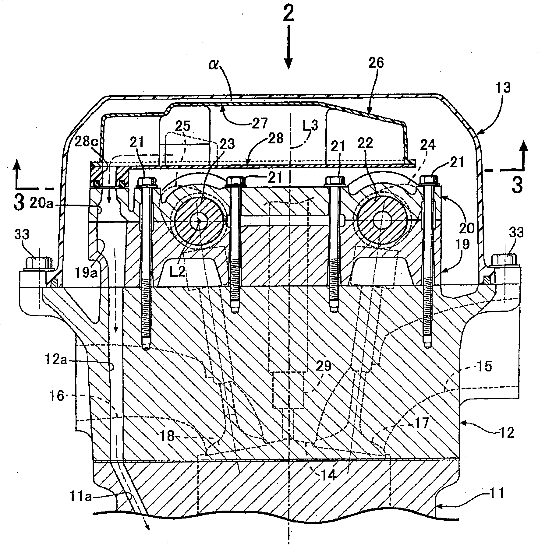
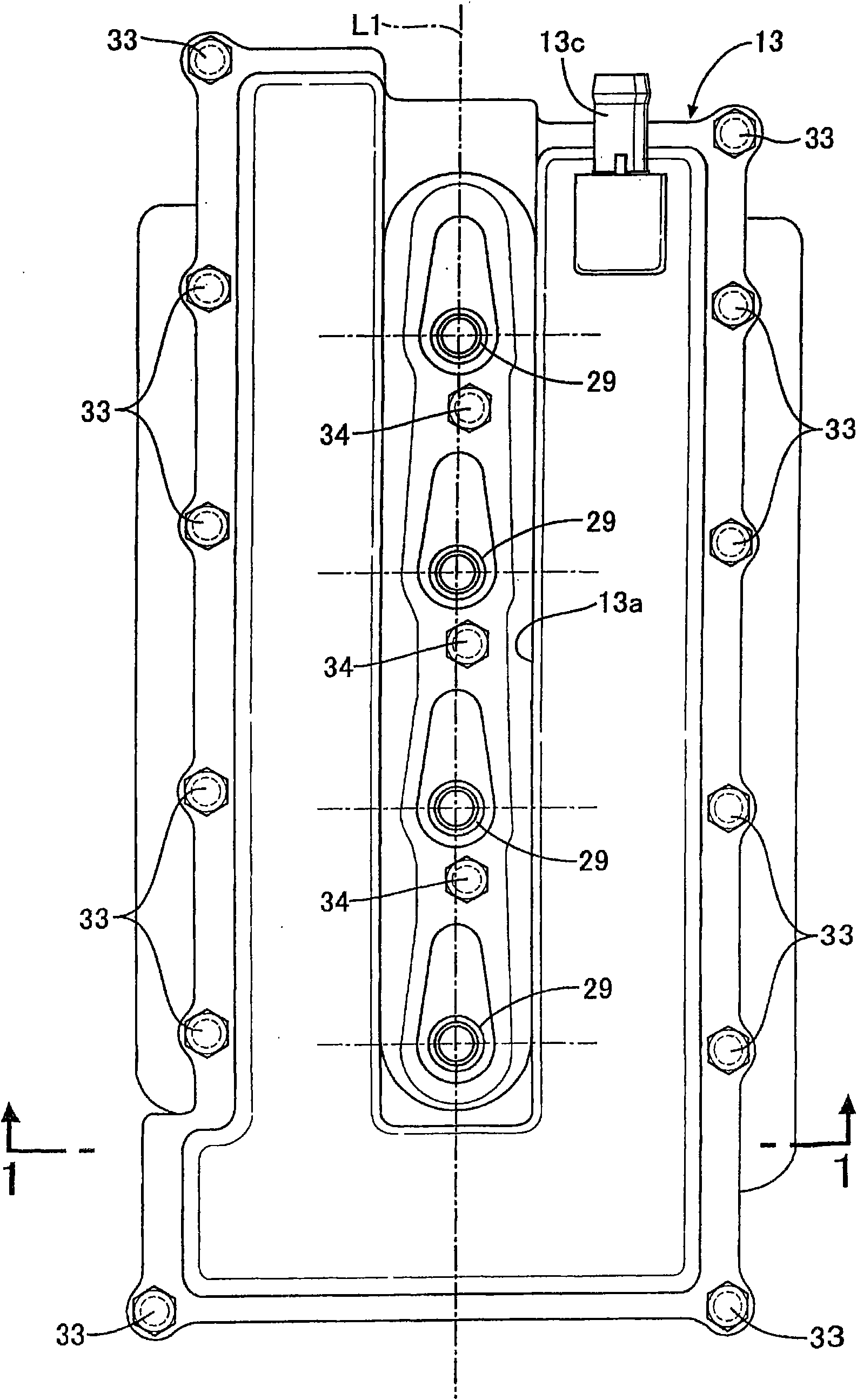
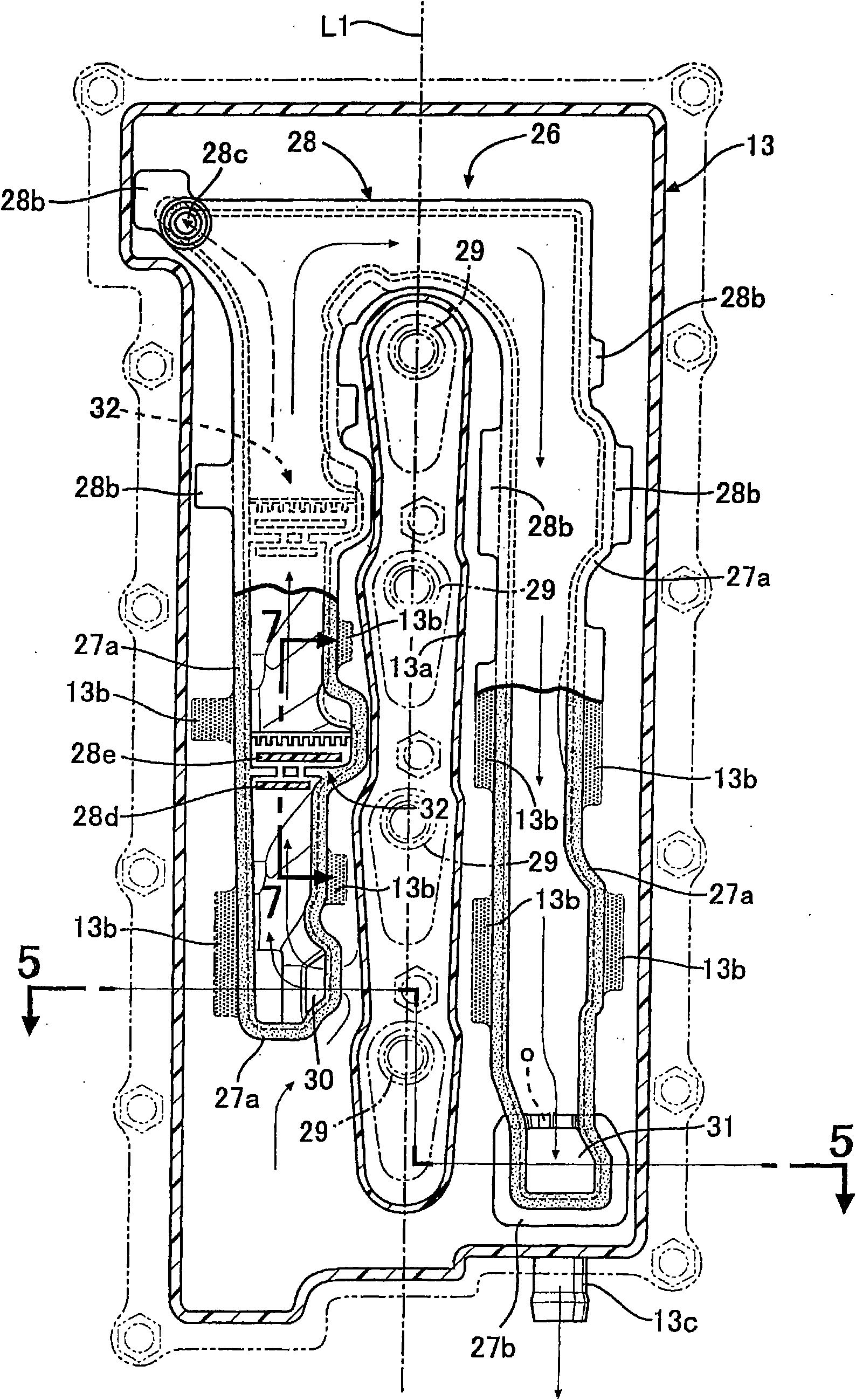
[0030] Figure 1 to Figure 8 Embodiments of the present invention are shown.

[0031] Such as figure 1 As shown, the cylinder head 12 is combined on the upper end of the cylinder block 11 of the in-cylinder injection fuel engine, and the cylinder head cover 13 is combined on the upper end of the cylinder head 12 . In this specification, the vertical direction is defined with the cylinder block 11 side as the lower side and the cylinder head cover 13 side as the upper side.

[0032] A combustion chamber 14, an intake port 15 and an exhaust port 16 connected to the combustion chamber 14 are formed in the cylinder head 12. The intake port 15 is opened and closed by the intake valve 17, and the exhaust port 16 is opened and closed by the exhaust valve 18. close. The camshaft holder 19 and the cover 20 overlap and are fastened on the upper surface of the cylinder head 12 by a plurality of bolts 21 . Between the retainer 19 and the cover 20 , an intake cam 24 is provided on the ...


PUM


Abstract

A breather device for an engine, in which a predetermined gap (a) is formed between an outer surface of a breather chamber (26) placed inside the head cover (13) and an inner surface of a head cover (13). The gap (a) functions as a heat insulation space even if outdoor air temperature drops, and this prevents freezing of blow-by gas in the breather chamber (26). In addition, a blow-by gas entrance(30) formed in a wall surface of the breather chamber (26) is opened at a position facing the inner surface of the head cover (13). This not only enhances the degree of positioning freedom for the blow-by gas entrance (30) to a levelhigher than that of a case where the blow-by gas entrance (30) is opened at a lower surface of the breather chamber (26) but also allows the gap (a) between the breather chamber (26) and the head cover (13) to exhibit a good oil separation effect, preventing the entry of oil into the breather chamber (26).

Description

technical field [0001] The present invention relates to a breather device for an engine that arranges a breather chamber inside a cylinder head cover coupled to a cylinder head of an engine, and separates oil contained in blow-by gas that flows back into an intake system through the breather chamber. A predetermined gap is formed between the outer surface of the breather chamber and the inner surface of the cylinder head cover. Background technique [0002] When the blow-by gas of the engine is returned to the intake system of the engine through the breather chamber provided in the cylinder head cover, the oil contained in the blow-by gas is separated in the breather chamber to prevent the oil from being mixed into the intake system. [0003] When the outside air temperature becomes low, the cylinder head cover of the engine becomes cold, so the blow-by gas arranged in the breather chamber inside the cylinder head cover freezes, and the passage of the blow-by gas may be bloc...

Claims


Application Information

Patent Timeline
Patent Type & Authority Applications(China)
IPC IPC(8): F01M13/00F01M13/04
CPCF01M2013/0455F01M13/022F01M13/0416F01M2013/0472F01M2013/0433
Inventor 工藤洋嗣岩崎良重
Owner HONDA MOTOR CO LTD
Learn More