A flywheel battery structure for an h-type electric vehicle

A flywheel battery, electric vehicle technology, applied in electric vehicles, electric components, motors, etc., can solve the problems affecting the stability of the flywheel battery system, the large axial length of the energy storage device, the large volume of the flywheel battery, etc., to suppress the gyro effect. , Enhance the system stability, the effect of large moment of inertia

Active Publication Date: 2021-02-12
JIANGSU UNIV
View PDF3 Cites 0 Cited by
  • Summary
  • Abstract
  • Description
  • Claims
  • Application Information

AI Technical Summary

Problems solved by technology

[0003] The motor, flywheel and magnetic bearing of the traditional flywheel battery system are independently arranged around the main shaft, which results in a larger flywheel battery, especially the commonly used magnetic bearing is a cylindrical structure, and when the flywheel rotor is disturbed by the outside, it is easy to produce a gyro effect, and the system is stable However, although the flywheel battery system supported by spherical magnetic bearings can suppress the gyro effect to a certain extent, instability still inevitably occurs due to the large axial length of the main shaft.
The disc flywheel battery device can better suppress the gyro effect due to its short inertial axis and disc flywheel structure, but the disc motor still drives the flywheel rotor through the motor shaft, so the "short axis" structure still belongs to the "axis" structure , will still produce a certain gyro effect, affecting the stability of the flywheel battery system
In addition, the suspension support system of the traditional disc-type flywheel battery device uses two-degree-of-freedom magnetic bearings and three-degree-of-freedom magnetic bearings distributed on the upper and lower sides of the flywheel axis for decentralized control, resulting in excessive axial length of the energy storage device and low integration.
However, the flywheel section of some existing shaftless flywheel battery support systems is a flat disc type, so the effective energy storage area is small, and the energy storage density is not high.

Method used


Image

  • A flywheel battery structure for an h-type electric vehicle
  • A flywheel battery structure for an h-type electric vehicle
  • A flywheel battery structure for an h-type electric vehicle

Examples


Embodiment Construction

[0024] The specific solutions of the present invention will be further described below in conjunction with the accompanying drawings, but the protection scope of the present invention is not limited thereto.

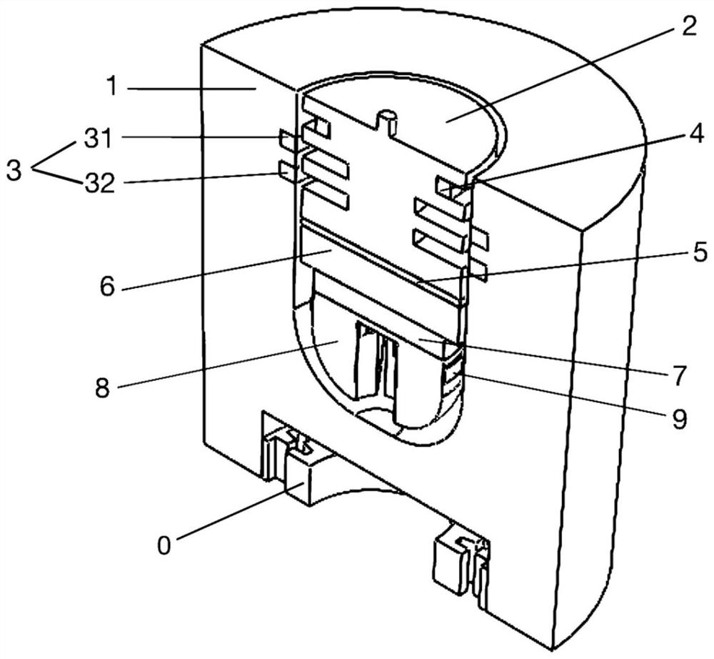
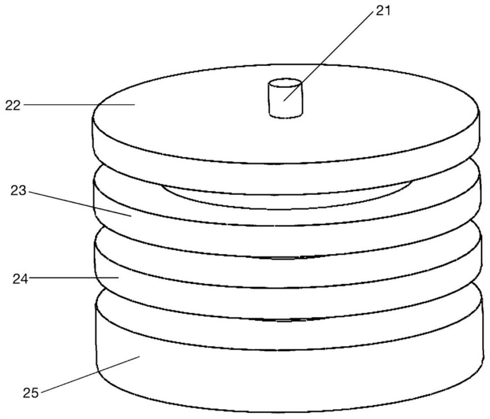
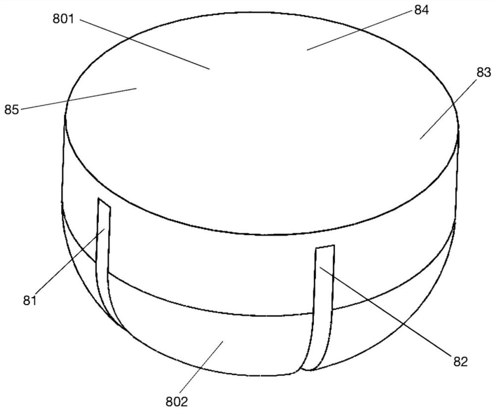
[0025] like figure 1 As shown, a flywheel battery structure for an H-type electric vehicle of the present invention includes a flywheel rotor casing 1, a stator shaft system 2, a permanent magnet 3, a radial winding 4, a magnetic isolation aluminum disc 5, a system connecting shaft 6, and a magnetic isolation aluminum Column 7, axial magnetic bearing core 8, axial winding 9 and motor / generator 0. like Image 6 As shown, the flywheel rotor casing 1 is cylindrical, the upper inner end is processed with an upper concave column 101, and the lower part of the upper concave column 101 is processed into a spherical surface 102, and the section of the upper concave column 101 and the spherical surface 102 is a U-shaped structure. Processed into the lower concave column 103, th...


PUM


Abstract

The invention discloses a novel H-type flywheel battery structure for electric vehicles. The interior of the flywheel rotor casing with an H-type cross section consists of a stator shaft system, a radial winding, a magnetic isolation aluminum plate, an axial magnetic bearing core, and an axial The winding is composed and fixed, and the outer part is the flywheel rotor. The permanent magnet is embedded in the flywheel rotor. The stability of the flywheel is ensured by the magnetic circuit formed with the radial winding, and the lower part of the flywheel is connected with the motor / generator rotor. By driving the flywheel to rotate, the motor The / generator achieves the effect of discharging / charging, and at the same time, the interaction between the axial magnetic bearing core and the axial winding can keep the bearing and flywheel stable under the condition that the double spherical surfaces are parallel. The present invention includes the whole device in the housing of the flywheel battery, increases the volume and weight of the flywheel rotor, thereby increasing the energy storage of the flywheel.

Description

technical field [0001] The invention relates to the technical field of flywheel batteries, in particular to a shaftless magnetic levitation flywheel battery structure, which is suitable for vehicle-mounted flywheel batteries. Background technique [0002] With the development of economy and society, automobiles have become an indispensable tool in people's daily life. However, a series of environmental problems caused by fuel vehicles cannot be ignored. Therefore, the promotion of new energy electric vehicles characterized by low energy consumption and no pollution has become an important means to solve this problem. Therefore, electric vehicles have gradually entered people's field of vision. As far as the current situation is concerned, the power batteries of electric vehicles are mainly chemical battery. Due to the disadvantages of chemical batteries such as low specific energy and specific power, long charging time, and short service life, the development of chemical ba...

Claims


Application Information

Patent Timeline
Patent Type & Authority Patents(China)
IPC IPC(8): H02K7/02
CPCH02K7/025Y02E60/16Y02T10/64
Inventor 张维煜程烨东杨启富朱熀秋
Owner JIANGSU UNIV
Why Eureka
Try Eureka