Rotary air valve type engine

A technology for rotary valves and engines, which is applied to rotary slide valves, engine components, machines/engines, etc. It can solve the problems of the overall height and weight of the engine that cannot be reduced, high cost, and low inflation efficiency.

Pending Publication Date: 2019-08-30
珠海城市职业技术学院 +1
View PDF9 Cites 0 Cited by
  • Summary
  • Abstract
  • Description
  • Claims
  • Application Information

AI Technical Summary

Problems solved by technology

[0002] At present, the valve mechanism of the four-stroke vehicle engine generally adopts the valve type. Over the years, the valve mechanism of the engine has developed many types, but the overall structure has not changed. The commonly used ones are side valve and overhead valve. The two forms, the side valve structure is simple, but the inflation efficiency is low, the flame propagation distance is long, and has been eliminated in the vehicle; the overhead valve and the side camshaft valve are a typical form of the valve mechanism, and the camshaft Arranged on the side of the cylinder, the higher position is called the middle camshaft, and the lower position is called the lower camshaft. The structure of the overhead camshaft mainly has three forms: rocker arm drive, swing arm drive, and direct drive. Due to the camshaft Vibration and reciprocating inertia force, the noise is relatively large, and the number of parts of the valve train is also large. The overall height and weight of the engine have not been reduced, and the cost is high.

Method used


Image

  • Rotary air valve type engine
  • Rotary air valve type engine
  • Rotary air valve type engine

Examples


Embodiment Construction

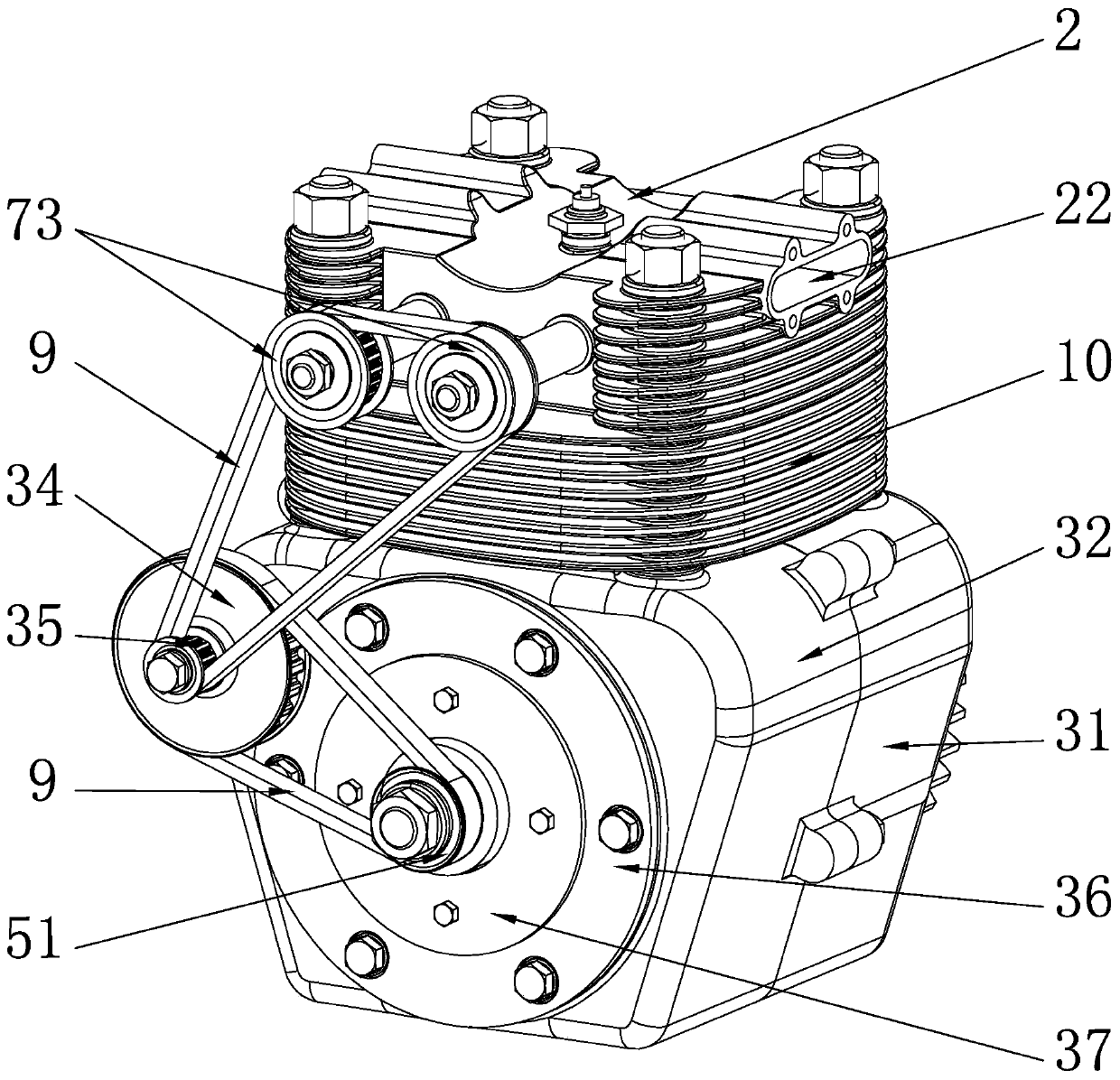
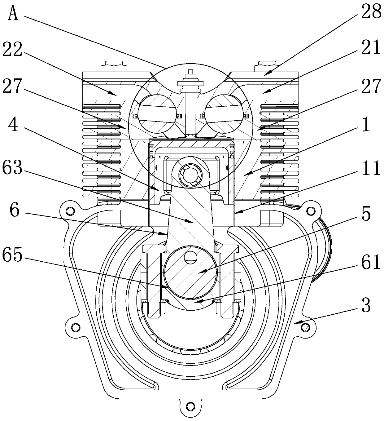
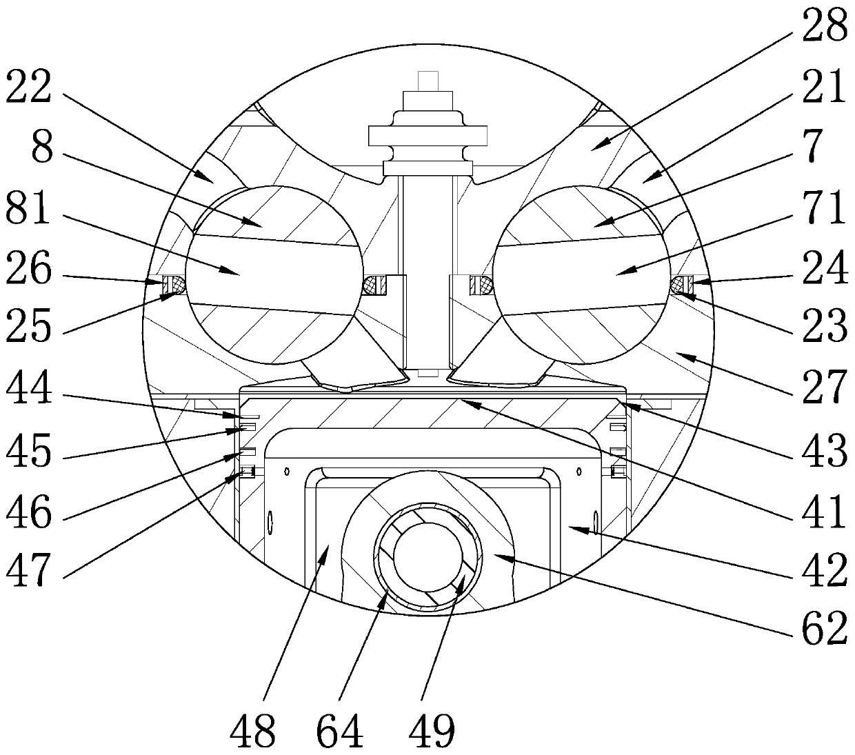
[0022] see figure 1 and figure 2 , a rotary valve engine of the present invention, comprising a cylinder block 1 and a cylinder head 2 arranged at the upper end of the cylinder block 1, a piston 4 is arranged in the cylinder block 1, and an air intake passage is arranged in the cylinder head 2 21 and exhaust passage 22, the cylinder head 2 is also equipped with a rotatable intake rotary valve 7 and an exhaust rotary valve 8, and the intake rotary valve 7 and exhaust rotary valve 8 are respectively opened radially through There are intake holes 71 and exhaust holes 81; when the intake rotary valve 7 rotates, the intake rotary valve 7 can communicate with the intake passage 21 and the cylinder block 1 through the intake holes 71, and the intake rotary valve 7 can also block the intake port. Air passage 21; when the exhaust rotary valve 8 rotates, the exhaust rotary valve 8 can communicate with the exhaust passage 22 and the cylinder block 1 through the exhaust hole 81, and the...


PUM


Abstract

The invention relates to the technical field of engines, and discloses a rotary air valve type engine. The rotary air valve type engine comprises a cylinder body and a cylinder cover arranged at the upper end of the cylinder body; a piston is arranged in the cylinder body; an air inlet channel and an air exhaust channel are arranged in the cylinder cover; an air inlet rotary valve and an air exhaust rotary valve which can rotate are further arranged in the cylinder cover; an air inlet hole and an air exhaust hole are respectively formed in the air inlet rotary valve and the air exhaust rotaryvalve in a radial penetrating mode; when the air inlet rotary valve rotates, the air inlet rotary valve can communicate with the air inlet channel and the cylinder body through the air inlet hole, andthe air inlet rotary valve can block the air inlet channel; and when the air exhaust rotary valve rotates, the air exhaust rotary valve can communicate with the air exhaust channel and the cylinder body through the air exhaust hole, and the air exhaust rotary valve can block the air exhaust channel. The air inlet rotary valve and the air exhaust rotary valve are used for replacing a complex valvestructure of an ordinary engine, so that the intake and exhaust of the engine are controlled, the structure is simple, and the quantity of parts of a valve mechanism of the engine is reduced. The cylinder cover structure is more compact, the size is smaller, and the processing cost of the engine is reduced.

Description

technical field [0001] The invention relates to the technical field of engines, in particular to a rotary valve engine. Background technique [0002] At present, the valve mechanism of the four-stroke vehicle engine generally adopts the valve type. Over the years, the valve mechanism of the engine has developed many types, but the overall structure has not changed. The commonly used ones are side valve and overhead valve. The two forms, the side valve structure is simple, but the inflation efficiency is low, the flame propagation distance is long, and has been eliminated in the vehicle; the overhead valve and the side camshaft valve are a typical form of the valve mechanism, and the camshaft Arranged on the side of the cylinder, the higher position is called the middle camshaft, and the lower position is called the lower camshaft. The structure of the overhead camshaft mainly has three forms: rocker arm drive, swing arm drive, and direct drive. Due to the camshaft Vibration...

Claims


Application Information

Patent Timeline
Patent Type & Authority Applications(China)
IPC IPC(8): F01L7/00F01L7/18F01L7/16F01L1/02
CPCF01L1/024F01L7/00F01L7/16F01L7/18
Inventor 赵新宽邓孟琦邓宝清张海磊杨卓李师航
Owner 珠海城市职业技术学院
Why Eureka
Try Eureka