Self-calibration method and device for structured light 3D depth camera

A technology of depth camera and structured light, which is applied in the fields of image processing, computer vision and artificial intelligence, can solve the problems of precision drop, optical axis offset, optical axis distortion, etc., and achieve the effect of real-time self-correction and improved robustness

Active Publication Date: 2021-02-26
XI AN JIAOTONG UNIV +1
View PDF8 Cites 0 Cited by
  • Summary
  • Abstract
  • Description
  • Claims
  • Application Information

AI Technical Summary

Problems solved by technology

The 3D depth camera developed based on structured light coding and decoding technology has a relatively simple stereo matching process and a small amount of calculation. However, to obtain high-precision depth information, high requirements are placed on assembly accuracy. Such conditions may cause the optical axis of the laser pattern projector or image sensor to shift, resulting in decreased depth accuracy, increased mismatch noise, etc.
Especially for the structured light 3D depth camera embedded in the smartphone, users will inevitably drop, collide, knock, etc. during the use of the mobile phone, which will easily cause the optical axis of the structured light depth camera to be distorted. How to solve this optical axis change It is particularly important to enhance the robustness of the mobile phone structured light 3D depth camera and realize a self-calibration technology for the structured light 3D depth camera due to the problems of decreased accuracy and increased noise.

Method used


Image

  • Self-calibration method and device for structured light 3D depth camera
  • Self-calibration method and device for structured light 3D depth camera
  • Self-calibration method and device for structured light 3D depth camera

Examples


Embodiment Construction

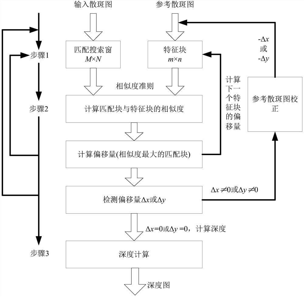
[0057] Attached below Figure 1-8 The self-calibration method and device of the present invention will be further described in detail.

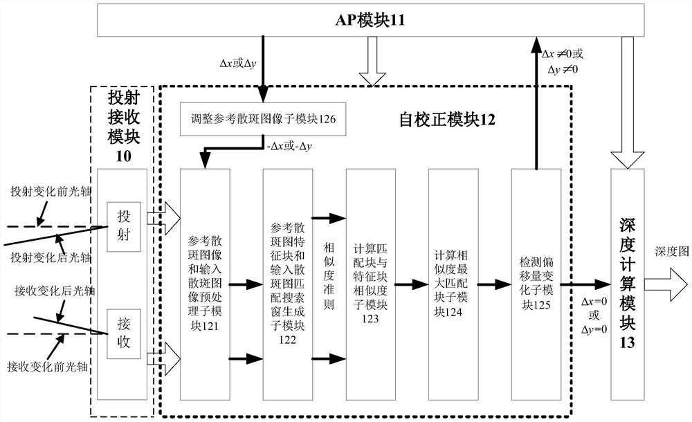
[0058] figure 1 It is a structural frame diagram of a structured light depth camera self-calibration device for a smart phone according to an embodiment of the present invention. Such as figure 1 As shown, the self-calibration device includes a projection receiving module 10 , an AP module 11 , a self-calibration module 12 and a depth calculation module 13 .

[0059] The projecting and receiving module 10 is configured to receive an input speckle image for depth calculation projected from an infrared laser speckle projector and collected by an image receiving sensor, and a reference speckle image.

[0060] The speckle image projected by the infrared laser speckle projector can be composed of a vertical cavity surface laser transmitter VCSEL combined with a collimating mirror and a diffractive optical device DOE, or a semiconductor laser LD...


PUM


Abstract

This disclosure proposes a self-calibration method and device for a structured light 3D depth camera. Due to the change in the optical axis of the laser coded graphic projector and the optical axis of the image receiving sensor, the deviation of the image block in the input coded image relative to the reference coded image is obtained. Shift, by adjusting the position of the reference coded image up and down through the changing offset, so that the center of the input coded image and the center of the reference coded image can form a self-feedback adjustment closed-loop system, so that the input coded image and the reference coded image are on the optical axis The optimal matching relationship can always be found when a large range of changes occurs. Further, depth calculation may also be performed according to the corrected offset. Compared with the prior art, the disclosed method and device can solve the problems of decreased depth accuracy and increased mismatch noise caused by changes in the optical axes of the laser coded graphic projector and the image receiving sensor, and realize real-time auto-automatic Correction to improve the robustness of the depth camera.

Description

technical field [0001] The invention belongs to the technical fields of image processing, computer vision and artificial intelligence, and in particular relates to a self-calibration method and device for a structured light 3D depth camera. Background technique [0002] Convenient and fast 3D reconstruction of scenes or objects is a hot topic in recent research. More and more 3D imaging technologies are emerging. In order to obtain real 3D images, it is necessary to calculate the depth information of scenes or objects, that is, depth perception. Depth perception technology is the core technology of 3D reconstruction, and has a wide range of applications and development prospects in the fields of machine vision, human-computer interaction, 3D printing, virtual reality, and smart phones. [0003] In the existing depth perception technology, the depth perception technology based on structured light coding and decoding can obtain more accurate depth information, and is not affec...

Claims


Application Information

Patent Timeline
Patent Type & Authority Patents(China)
IPC IPC(8): H04N13/246G06V10/145
CPCG06T3/60G02B27/48G06T7/521G06T7/55G06V10/145G06V10/757G06T7/74G06T2207/10028H04M1/0202G06T3/20G01C3/08G06F18/22
Inventor 葛晨阳谢艳梅姚慧敏周炳张康铎左龙
Owner XI AN JIAOTONG UNIV
Why Eureka
Try Eureka