
Full-speed range position sensorless improvement control method of large-power hub motor

A technology of in-wheel motor and control method, which is applied in motor control, motor generator control, AC motor control and other directions, can solve the problems of excessive occupation of software and hardware resources of the control system, affecting the normal driving of the vehicle, and unable to control the motor normally, etc. Save software and hardware resources, improve the effect significantly, and reduce the effect of the operating range

Inactive Publication Date: 2019-08-27
ARMOR ACADEMY OF CHINESE PEOPLES LIBERATION ARMY
View PDF2 Cites 6 Cited by
  • Summary
  • Abstract
  • Description
  • Claims
  • Application Information

AI Technical Summary

Problems solved by technology

[0002] In the full speed range, in order to make full use of the advantages of the pulse vibration injection method and the MRAS method, it is necessary to design a reasonable switching method so that the two algorithms can achieve effective switching and ensure that the motor achieves a smooth transition during the switching process. Otherwise, it is easy to cause the algorithm The inaccurate position acquisition during the switching process leads to the failure to control the motor normally, which in turn affects the normal driving of the vehicle. The following problems exist when switching between different identification algorithms. The switching involves the conversion of the speed and position angle, and the two algorithms need to be run simultaneously in the full speed range. To ensure the stability of the system when switching, this leads to excessive occupation of the software and hardware resources of the control system

Method used


Image

  • Full-speed range position sensorless improvement control method of large-power hub motor
  • Full-speed range position sensorless improvement control method of large-power hub motor
  • Full-speed range position sensorless improvement control method of large-power hub motor

Examples


Embodiment 1

[0038] see Figure 1-10 , the present invention provides a kind of technical scheme:

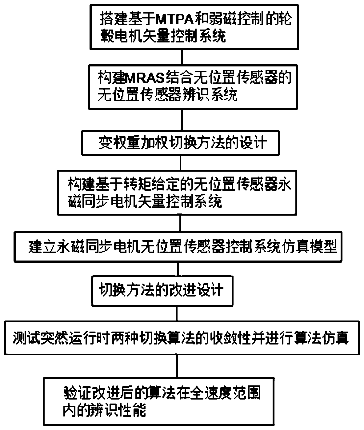
[0039] An improved control method without a position sensor in the full speed range of a high-power in-wheel motor, such as figure 1 shown, including the following steps:

[0040] S1: Establish mathematical models in different coordinate systems, analyze the mathematical models of PMSM in different coordinate systems, and combine the control requirements of the in-wheel motors of electric drive armored vehicles, take the torque value as the control amount, and combine with SVPWM technology to build a system based on MTPA and In-wheel motor vector control system for field weakening control to achieve high-performance control of the motor; including the following steps:

[0041] A: Mathematical modeling of PMSM in a-b-c coordinate system;

[0042] B: Mathematical modeling of PMSM in α-β and d-q coordinate systems;

[0043] S2: Build a position sensorless identification system combined with...


PUM


Abstract

The invention discloses a full-speed range position sensorless improvement control method of a large-power hub motor, and belongs to the field of a motor control method. The full-speed range positionsensorless improvement control method comprises the following steps of S1, building an MTPA and weak flux control-based hub motor vector control system; S2, building a position sensorless identification system of an MRAS combined with position sensorless; S3, designing a variable-weight weighing switching method; S4, building a given torque-based position sensorless permanent-magnet synchronous motor vector control system; S5, building a simulation model of the position sensorless permanent-magnet synchronous motor vector control system, and performing simulation verification; S6, improving and designing the switching method; S7, testing convergence of two switching algorithms during abrupt running, and performing algorithm simulation; and S8, verifying the identification performance of the improved algorithm within a full-speed range. By switching of two position identification algorithms, the working zone of the two algorithms is reduced on the basis of ensuring identification accuracy, and software and hardware resources are saved.

Description

technical field [0001] The invention relates to the field of motor control methods, in particular to an improved control method without a position sensor in the full speed range of a high-power wheel hub motor. Background technique [0002] In the full speed range, in order to make full use of the advantages of the pulse vibration injection method and the MRAS method, it is necessary to design a reasonable switching method, so that the two algorithms can achieve effective switching and ensure smooth transition of the motor during the switching process. Otherwise, it is easy to cause the algorithm The inaccurate position acquisition during the switching process leads to the inability to control the motor normally, which in turn affects the normal driving of the vehicle. The following problems exist when switching between different identification algorithms. The switching involves the conversion of rotational speed and position angle, and both algorithms need to be run at the s...

Claims


Application Information

Patent Timeline
Patent Type & Authority Applications(China)
IPC IPC(8): H02P21/24H02P21/00H02P21/18H02P25/022H02P6/34
CPCH02P6/34H02P21/0003H02P21/0021H02P21/18H02P21/24H02P25/022H02P2207/05
Inventor 廖自力袁东赵其进刘春光宋小庆张运银魏曙光陈克伟蔡立春解建一陈路明高强徐浩轩
Owner ARMOR ACADEMY OF CHINESE PEOPLES LIBERATION ARMY
Learn More