Yarn rapid waxing device
A yarn and fast technology, applied in the field of fast yarn waxing devices, can solve the problems of insufficient uniform waxing and waste of labor, and achieve the effects of saving labor, uniform waxing, and avoiding wear and tear
- Summary
- Abstract
- Description
- Claims
- Application Information
AI Technical Summary
Problems solved by technology
Method used
Image

Examples
Embodiment 1
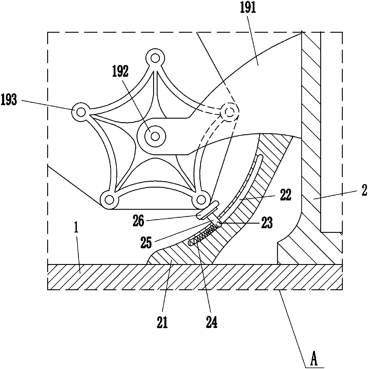
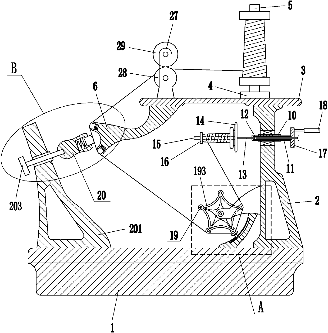
[0016] A quick waxing device for yarn, such as Figure 1-3 As shown, it includes a base 1, a vertical plate 2, a top plate 3, a shaft sleeve 4, a sleeve rod 5, a connecting plate 6, a first spring 8, a first block 9, a hollow tube 10, a sliding frame 11, a sliding block 12, Moving rod 13, disc 14, first screw rod 15, first nut 16, turntable 17, handle 18 and guiding mechanism 19, the right side of the top of the base 1 is bolted with a supporting vertical plate 2, and the top of the vertical plate 2 is fixed There is a top plate 3, and the vertical plate 2 is connected with the top plate 3 through bolt connection, the shaft sleeve 4 is bolted to the top right side of the top plate 3, and the sleeve rod 5 for placing is installed in the shaft sleeve 4, and the bottom left side of the top plate 3 is fixed There is a connecting plate 6, and the top plate 3 is connected with the connecting plate 6 by means of bolt connection. The upper and lower sides of the left side of the conne...
Embodiment 2
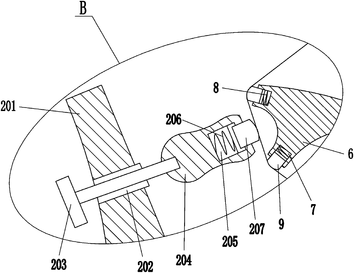
[0018] A quick waxing device for yarn, such as Figure 1-3 As shown, it includes a base 1, a vertical plate 2, a top plate 3, a shaft sleeve 4, a sleeve rod 5, a connecting plate 6, a first spring 8, a first block 9, a hollow tube 10, a sliding frame 11, a sliding block 12, Moving rod 13, disc 14, first screw rod 15, first nut 16, turntable 17, handle 18 and guiding mechanism 19, the right side of the top of the base 1 is bolted with a supporting vertical plate 2, and the top of the vertical plate 2 is fixed There is a top plate 3, and the shaft sleeve 4 is bolted to the top right side of the top plate 3. A sleeve rod 5 for placement is installed in the shaft sleeve 4. A connecting plate 6 is fixedly connected to the left side of the bottom of the top plate 3. The upper and lower sides of the left side of the connecting plate 6 The sides are all provided with a square mounting groove 7, and the connecting plate 6 on the right side in the mounting groove 7 is connected with a f...
Embodiment 3
[0021] A quick waxing device for yarn, such as Figure 1-3 As shown, it includes a base 1, a vertical plate 2, a top plate 3, a shaft sleeve 4, a sleeve rod 5, a connecting plate 6, a first spring 8, a first block 9, a hollow tube 10, a sliding frame 11, a sliding block 12, Moving rod 13, disc 14, first screw rod 15, first nut 16, turntable 17, handle 18 and guiding mechanism 19, the right side of the top of the base 1 is bolted with a supporting vertical plate 2, and the top of the vertical plate 2 is fixed There is a top plate 3, and the shaft sleeve 4 is bolted to the top right side of the top plate 3. A sleeve rod 5 for placement is installed in the shaft sleeve 4. A connecting plate 6 is fixedly connected to the left side of the bottom of the top plate 3. The upper and lower sides of the left side of the connecting plate 6 The sides are all provided with a square mounting groove 7, and the connecting plate 6 on the right side in the mounting groove 7 is connected with a f...
PUM
 Abstract
Description
Claims
Application Information
 - Generate Ideas
- Intellectual Property
- Life Sciences
- Materials
- Tech Scout
- Unparalleled Data Quality
- Higher Quality Content
- 60% Fewer Hallucinations
Browse by: Latest US Patents, China's latest patents, Technical Efficacy Thesaurus, Application Domain, Technology Topic, Popular Technical Reports.
© 2025 PatSnap. All rights reserved.Legal|Privacy policy|Modern Slavery Act Transparency Statement|Sitemap|About US| Contact US: help@patsnap.com