Single-oil-cylinder drive device

A driving device and a single oil cylinder technology, applied in the field of injection molding machine manufacturing, can solve problems such as the inability to realize screw melting and glue processing, and achieve the effects of ingenious structural design, reduction of production costs, and elimination of cumbersome steps.

Inactive Publication Date: 2019-08-27
浙江台意德塑机制造有限公司
View PDF1 Cites 1 Cited by
  • Summary
  • Abstract
  • Description
  • Claims
  • Application Information

AI Technical Summary

Problems solved by technology

However, the oil injection cylinder of this device only has two working states of push and pull, and it is impossible to realize the screw rotation for melt processing, so the structure of this device needs to be further improved

Method used


Image

  • Single-oil-cylinder drive device
  • Single-oil-cylinder drive device
  • Single-oil-cylinder drive device

Examples


Embodiment Construction

[0034] The present invention will be further described in detail below in conjunction with the accompanying drawings and embodiments.

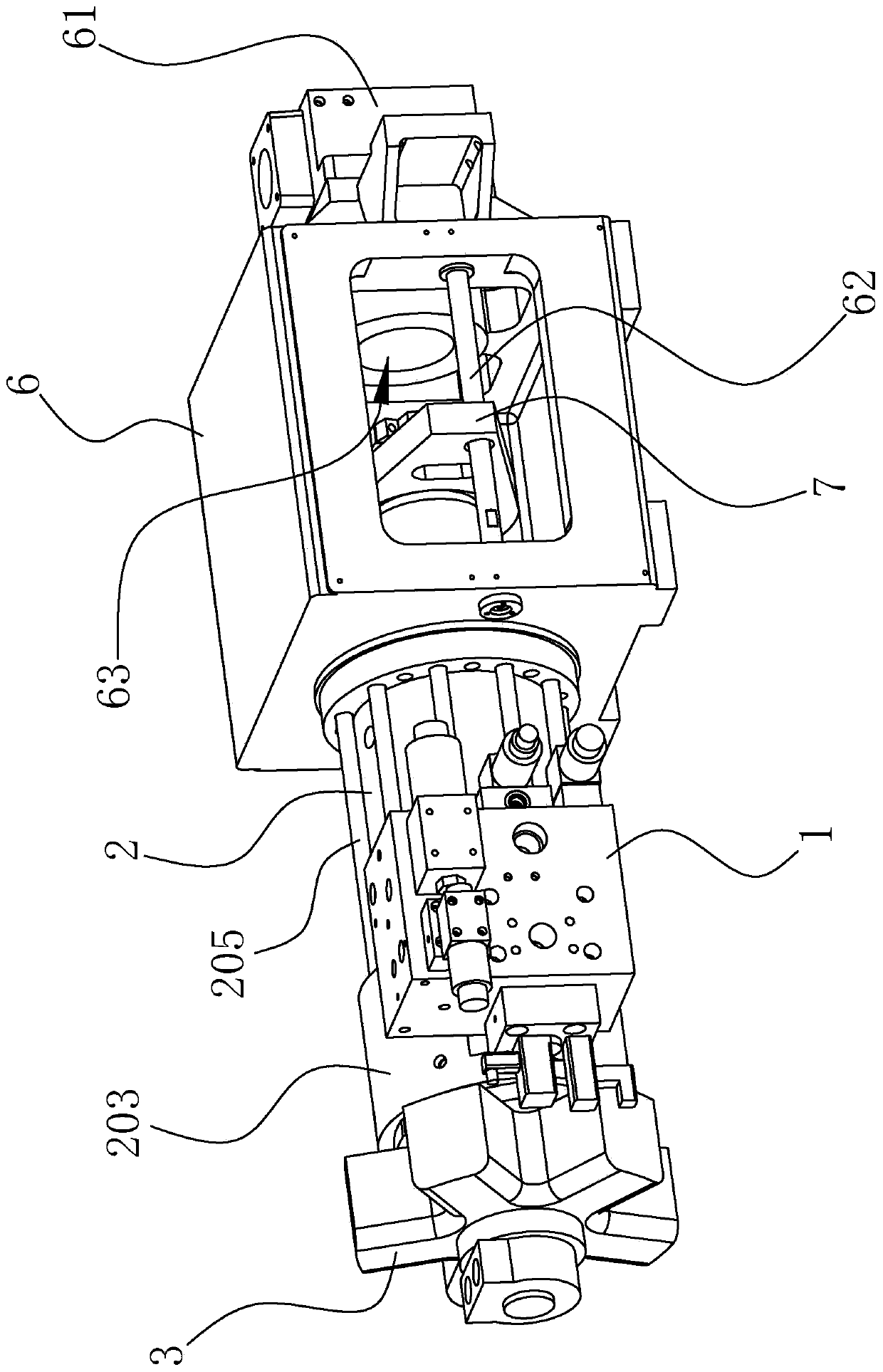
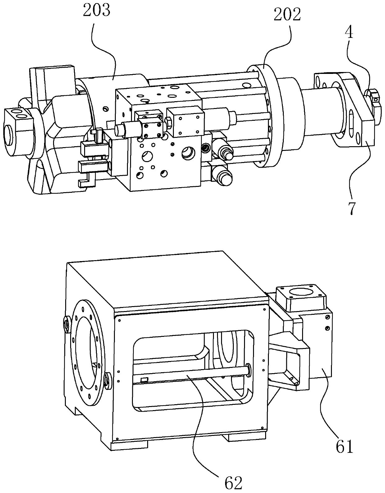
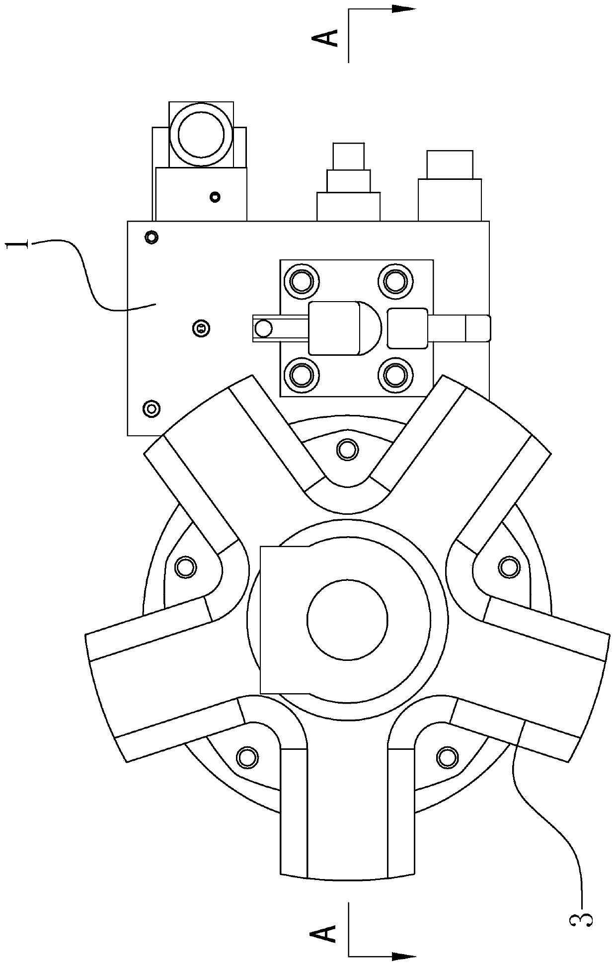
[0035] Such as Figure 1 to Figure 19As shown, the single oil cylinder driving device of this embodiment includes an oil cylinder 2 and an oil cylinder driving module. A transmission seat 4 capable of connecting an injection molding screw is arranged at the end of the piston rod 26 of the oil cylinder 2, and the propulsion chamber 21 of the oil cylinder 2 is connected to the return The retreat chamber 22 communicates with the cylinder drive module through pipelines respectively, and the cylinder drive module is used to change the oil pressure difference between the advance chamber 21 and the retreat chamber 22 to drive the piston rod 26 to advance and retreat. The seal is provided with a rotating mechanism, one end of the rotating mechanism is connected to the piston rod 26 in transmission, and the piston rod 26 can slide back and forth relati...


PUM


Abstract

A single-oil-cylinder drive device comprises an oil cylinder and an oil cylinder drive module. A transmission seat is arranged at the end of a piston rod of the oil cylinder, and a propulsion cavity and a retreating cavity communicate with the oil cylinder drive module through pipelines. A rotation mechanism is arranged in the propulsion cavity in a sealed manner, one end of the rotation mechanismis in transmission connection with a piston rod, and the piston rod can slide back and forth relative to the rotation mechanism. The other end of the rotation mechanism extends out of the oil cylinder and is in transmission connection with a hydraulic motor. The hydraulic motor is used for driving the rotation mechanism to drive the piston rod to rotate relative to an oil cylinder block, and thehydraulic motor communicates with the oil cylinder drive module through the pipeline. The oil cylinder drive module is connected with the control module through a line. The oil cylinder drive module can be controlled by the control module to switch to drive the piston rod to move forward and backward and drive an output shaft of the hydraulic motor to rotate. The single-oil-cylinder drive device has the advantages that the control module controls oil channels to be automatically switched, the injection molding efficiency is high, the drive module can both push and pull a lead screw to conductinjection molding and drive the lead screw to rotate for rubber melting, and the use effect is good.

Description

technical field [0001] The invention relates to the technical field of manufacturing an injection molding machine, in particular to a single oil cylinder driving device for an injection molding machine. Background technique [0002] There is an existing Chinese invention patent application with the application number CN201310372794.X titled "A New Type of Injection Cylinder Device for Injection Molding Machine" which discloses a new type of injection cylinder device for injection molding machine, including injection head plate, injection piston rod, injection Piston end cover, injection seat, injection piston, injection cylinder body, injection rod, injection cylinder bottom, injection cylinder rod, injection cylinder cover, material storage cylinder; the characteristics are: the material storage cylinder is fixed to the injection head plate hole, The injection cylinder cover is fixed on one end of the injection cylinder body and fixed to the injection seat through multiple ...

Claims


Application Information

Patent Timeline
IPC IPC(8): B29C45/54B29C45/17
CPCB29C45/17B29C45/531B29C45/54
Inventor 孙吉郑邦连
Owner 浙江台意德塑机制造有限公司
Why Eureka
Try Eureka