
Electric spindle system provided with oscillating heat pipe and heat-structure coupling characteristic modeling method thereof

A technology of oscillating heat pipes and modeling methods, applied in the field of machinery, can solve problems such as thermal deformation, research on electric spindle systems, failure to predict the life of parts such as electric spindle bearings, etc., to reduce errors, ensure modeling accuracy, and good heat transfer performance effect

Inactive Publication Date: 2019-08-23
CHONGQING UNIV
View PDF5 Cites 4 Cited by
  • Summary
  • Abstract
  • Description
  • Claims
  • Application Information

AI Technical Summary

Problems solved by technology

However, during the machining process of machine tools, such as frictional heat generation of rolling bearings, many factors will cause uneven distribution of temperature field in the feed system and cause thermal deformation, which will affect the machining accuracy of CNC machine tools.
The life of the parts of the electric spindle is affected by temperature and thermal displacement. However, there is no way to study the fine modeling of the temperature and thermal displacement changes of the electric spindle system, let alone predict the life of the electric spindle bearings and other components.

Method used


Image

  • Electric spindle system provided with oscillating heat pipe and heat-structure coupling characteristic modeling method thereof
  • Electric spindle system provided with oscillating heat pipe and heat-structure coupling characteristic modeling method thereof
  • Electric spindle system provided with oscillating heat pipe and heat-structure coupling characteristic modeling method thereof

Examples


Embodiment Construction

[0050] Hereinafter, preferred embodiments of the present invention will be described in detail with reference to the accompanying drawings. It should be understood that the preferred embodiments are only for illustrating the present invention, but not for limiting the protection scope of the present invention.

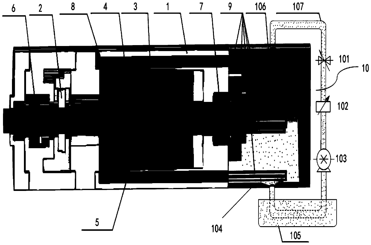
[0051] The invention provides an electric spindle system configured with an oscillating heat pipe, such as figure 1 As shown, it includes a main shaft housing 1, an encoder 2, a motor stator 3, and a motor rotor 4. It also includes a main shaft 5, which is arranged inside the main shaft housing 1, and a front bearing 6 and a rear bearing 7 to realize the connection between the main shaft 5 and the main shaft housing. 1 is fixed, the main shaft 5 is connected with the motor rotor 4 to realize the rotation of the main shaft 5, a cooling water jacket 8 is arranged on the outer surface of the motor stator 3, and an oscillating heat pipe is arranged inside the main shaft 5 ...


PUM


Abstract

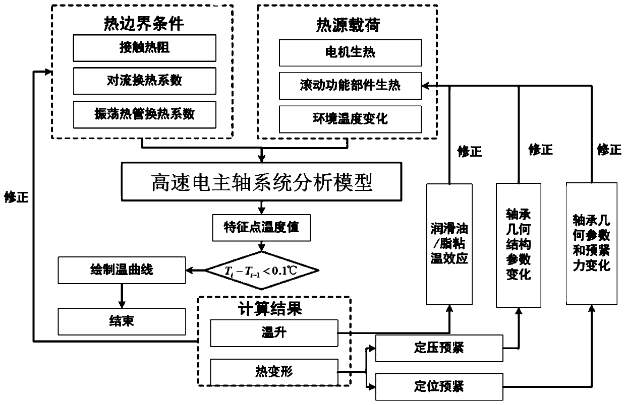
The invention discloses an electric spindle system provided with an oscillating heat pipe and a heat-structure coupling characteristic modeling method thereof. The electric spindle system comprises amain shaft which is arranged in the main shaft shell; a front bearing and a rear bearing which can achieve fixation of the main shaft and the main shaft shell, wherein the main shaft is connected witha motor rotor to achieve rotation of the main shaft; a cooling water jacket is arranged in the main shaft, whrein an oscillation heat pipe is arranged between the cooling water jacket and the main shaft shell; and a cooling device which is connected with one end of the main shaft shell. The electric spindle system provided with oscillating heat pipes has good heat exchange performance. The modeling method of the electric spindle system adopts a finite element method to analyze the heat of a high-speed motorized spindle system. The modeling method uses the finite element method to analyze thethermal-structural coupling characteristics of the high-speed electric spindle system with the oscillating heat pipe. The advantage lies in simulating the working state of the electric spindle system.By correcting the heat source load and thermal boundary conditions, the precise finite element model is used to reduce the error of the heat-structure coupling characteristic modeling of the high-speed spindle system provided with the oscillating heat pipe so as to make the finite element analysis result be closer to the actual value.

Description

technical field [0001] The invention relates to the mechanical field, and in particular relates to a system for configuring an oscillating heat pipe electric spindle and a modeling method thereof. Background technique [0002] The electric spindle is a new technology that integrates the machine tool spindle and the spindle motor in the field of CNC machine tools. The spindle is a set of components, which includes the electric spindle itself and its accessories: electric spindle, high-frequency frequency conversion device, oil mist lubricator, cooling device, built-in encoder, tool changer, etc. This type of transmission structure in which the spindle motor and the machine tool spindle are "combined into one" makes the spindle components relatively independent from the transmission system and the overall structure of the machine tool, so it can be made into a "spindle unit", commonly known as "electric spindle", with characteristics The structure with high speed, high precis...

Claims


Application Information

Patent Timeline
IPC IPC(8): G06F17/50
CPCG06F2119/08G06F30/20
Inventor 马驰刘佳兰王时龙
Owner CHONGQING UNIV
Learn More