
Laser shock peening device and method

A technology of laser shock strengthening and light guide device, which is applied in the field of metal surface treatment, can solve the problems of low efficiency of laser shock strengthening, etc., and achieves the effects of reducing volume and weight, high frequency, and improving the scope of application

Pending Publication Date: 2019-08-23
西安天瑞达光电技术股份有限公司
View PDF0 Cites 7 Cited by
  • Summary
  • Abstract
  • Description
  • Claims
  • Application Information

AI Technical Summary

Problems solved by technology

[0004] The purpose of the present invention is to at least solve the problem of low laser shock peening efficiency

Method used


Image

  • Laser shock peening device and method
  • Laser shock peening device and method
  • Laser shock peening device and method

Examples


Embodiment Construction

[0031] Exemplary embodiments of the present disclosure will be described in more detail below with reference to the accompanying drawings. Although exemplary embodiments of the present disclosure are shown in the drawings, it should be understood that the present disclosure may be embodied in various forms and should not be limited by the embodiments set forth herein. Rather, these embodiments are provided for more thorough understanding of the present disclosure and to fully convey the scope of the present disclosure to those skilled in the art.

[0032] It should be understood that the terminology used herein is for the purpose of describing particular example embodiments only and is not intended to be limiting. As used herein, the singular forms "a", "an" and "the" may also be meant to include the plural forms unless the context clearly dictates otherwise. The terms "comprising", "comprising", "containing" and "having" are inclusive and thus indicate the presence of stated...


PUM

PropertyMeasurementUnit
Diameteraaaaaaaaaa

Abstract

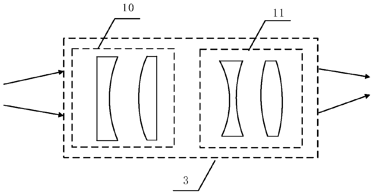
The invention relates to the field of metal surface treatment, in particular to a laser shock peening device. The laser shock peening device comprises a high-repetition-frequency low-energy laser, a light guide device, a focusing device, a constrained layer loading device and a metal part, wherein one end of the light guide device is connected with the high-repetition-frequency low-energy laser, and the other end of the light guide device is connected with the focusing device; the constrained layer loading device forms a constrained layer on the surface of the metal part; a light spot output by the focusing device penetrates through the constrained layer and act on the surface of the metal part. According to the laser shock peening device, the high-repetition-frequency low-energy laser shock peening method is adopted, the frequency is relatively high, and the processing efficiency is greatly improved.

Description

technical field [0001] The invention belongs to the field of metal surface treatment, and in particular relates to a laser shock strengthening method and device. Background technique [0002] Laser shock peening technology, also known as laser peening, uses short pulses (ns level) and high peak power density (10 9 W / cm 2 Above) the laser penetrates the constrained layer and impacts the laser-absorbing protective film covering the metal surface, generating a high-voltage transient plasma shock wave. The shock wave pressure as high as GPa causes high-strain plastic deformation on the surface of the metal material, forming a large residual compressive stress. The microstructure undergoes great changes, which can significantly improve the fatigue performance of metal materials such as external force damage and corrosion resistance. [0003] At present, laser shock strengthening methods mostly use high-energy nanosecond lasers for laser shock strengthening. According to the inv...

Claims


Application Information

Patent Timeline
IPC IPC(8): C21D10/00
CPCC21D10/005
Inventor 李国杰何艳磊程江勇薛鹏波刘元伟毋乃靓何强世
Owner 西安天瑞达光电技术股份有限公司
Learn More