
Bottom-blowing flow dynamic control method of top-bottom combined blowing converter

A top-bottom blowing, flow dynamic technology, applied in steel manufacturing process, manufacturing converter, process efficiency improvement and other directions, can solve problems such as inability to adjust, switching timing is advanced or delayed, affecting bottom blowing effect, etc., to achieve improvement Metallurgical effect, reducing carbon and oxygen accumulation, improving quality effect

Inactive Publication Date: 2019-08-23
山东钢铁集团有限公司
View PDF5 Cites 6 Cited by
  • Summary
  • Abstract
  • Description
  • Claims
  • Application Information

AI Technical Summary

Problems solved by technology

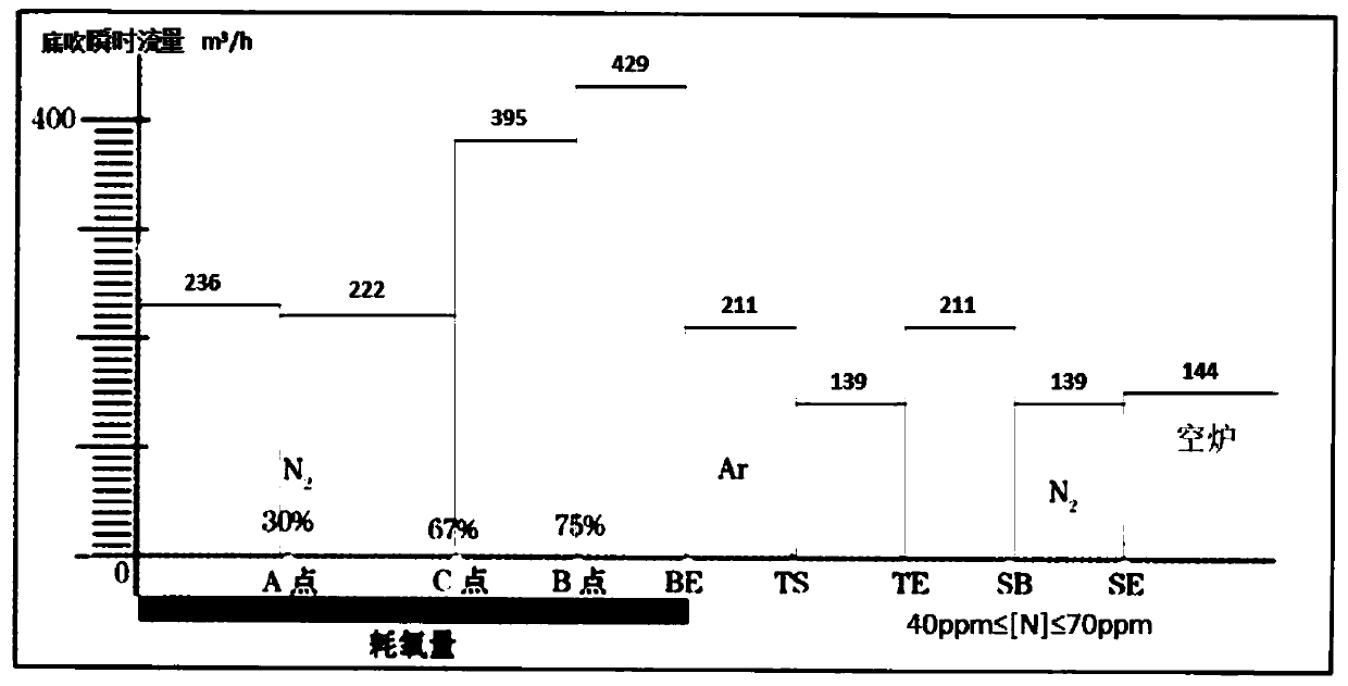
[0003] The traditional bottom blowing control system is basically divided into three modes: full blowing argon, nitrogen and argon switching, and full nitrogen blowing according to the requirements of the nitrogen content of the steel type. The set total oxygen consumption and bottom blowing parameters cannot be dynamically corrected. When the charging system, molten iron conditions, blowing conditions, etc. change, the process control (such as decarburization speed, back-drying and splashing period, etc.) will also change greatly, which means that the switching timing will be advanced or delayed, which will affect bottom blowing effect; at the same time, the flow value at each stage is basically unchanged and cannot be adjusted flexibly according to actual needs; at the same time, the instantaneous flow rate and switching timing of the bottom blowing of the traditional control system only take into account the requirements of the nitrogen content of molten steel, according to The nitrogen content requirements of steel types simply distinguish three bottom blowing modes, but deviate from the true meaning of the metallurgical effect of top and bottom combined blowing converter blowing, which limits the better play of the metallurgical function of top and bottom blowing

Method used


Image

  • Bottom-blowing flow dynamic control method of top-bottom combined blowing converter
  • Bottom-blowing flow dynamic control method of top-bottom combined blowing converter
  • Bottom-blowing flow dynamic control method of top-bottom combined blowing converter

Examples


Embodiment 1

[0110] Nitrogen and argon switching mode + medium flow series, and the average value of the converter end point of the first 10 furnaces measured by the sub-lance: [C] content: 0.082wt%, [O] content: 310ppm, molten pool liquid level 892cm, temperature T = 1651℃ and the furnace age of the next furnace to be blown is 9865 furnaces; the variable parameters are brought into formula (2), and the actual injection value of the bottom blowing instantaneous flow in 8 time intervals of present embodiment 1 is calculated, see for details Table 1 below:

[0111] Table 1 The actual injection value of the instantaneous flow rate of the bottom blowing in the 8 time intervals under the nitrogen and argon switching mode + medium flow series

[0112] group F 中1

Embodiment 2

[0114] Nitrogen and argon switching mode + high flow series, and the average value of the converter end points of the first 10 furnaces measured by the sub-lance: [C] content: 0.091wt%, [O] content: 276ppm, molten pool liquid level: 880cm, temperature T = 1645 ℃; and the furnace age of the next furnace to be blown is 9868 furnaces; the variable parameters are brought into the formula (3), and the actual injection value of the bottom blowing instantaneous flow rate in the 8 time intervals of this embodiment 2 is calculated. See Table 2 below:

[0115] Table 2 The actual injection value of the instantaneous flow rate of the bottom blowing in the 8 time intervals under the nitrogen and argon switching mode + high flow series

[0116] group F 高1

Embodiment 3

[0118] Full argon blowing mode + low flow series, and the average value of the converter end point of the first 10 furnaces measured by the sub-lance: [C] content: 0.062wt%, [O] content: 412ppm, molten pool liquid level: 876cm, temperature T = 1639 ℃; and the furnace age of the next furnace to be blown is 9870 furnaces; the variable parameters are brought into the formula (1), and the actual injection value of the bottom blowing instantaneous flow rate in the 8 time intervals of this embodiment 3 is calculated. See Table 3 below:

[0119] Table 3 The actual injection value of the instantaneous flow rate of the bottom blowing in the 8 time intervals under the full argon blowing mode + low flow series

[0120] group F 低1

[0121] The methods and devices not described in detail in the present invention are all prior art and will not be repeated here.


PUM


Abstract

The invention provides a bottom-blowing flow dynamic control method of a top-bottom combined blowing converter. Firstly, three flow series composed of a high-flow series, a medium-flow series and a low-flow series are added based on three bottom-blowing air supply modes, three bottom blowing air supply modes and three flow series are permuted and combined into nine basic bottom-blowing curves, wherein the time coordinate axes of the basic bottom-blowing curves are provided with eight time intervals; in addition, the measured carbon content [C], the oxygen content [O], a molten pool liquid level a, and an end point temperature T of the converter blowing end point of the previous furnace as well as the furnace age of a next furnace to be blown are taken as variable parameters to be substituted into a formula, then the nine basic bottom blowing curves are dynamically corrected through formula calculation, thus the bottom blowing instantaneous flow after dynamic correction is the bottom blowing instantaneous flow of the actual blowing of the next furnace. According to the bottom-blowing flow dynamic control method of the top-bottom combined blowing converter, the problem that the bottom blowing flow is fixed is solved, the dynamic control of the bottom blowing flow is realized, thus reducing the carbon oxygen product at the blowing end point and improving the metallurgical effect of the bottom blowing as well as the quality of the molten steel.

Description

technical field [0001] The invention relates to the technical field of converter steelmaking, in particular to a method for dynamically controlling the flow rate of bottom blowing in a converter with combined top and bottom blowing. Background technique [0002] The metallurgical effect of converter top-bottom combined blowing lies in: accelerating the decarburization reaction, reducing the critical carbon content when the decarburization speed characteristic changes; reducing the metal content in the slag; reducing the oxygen content in the steel; increasing the residual manganese content in the molten steel; saving alloy ; Reduce the amount of lime, dolomite, etc.; increase the yield of molten steel, etc. [0003] The traditional bottom blowing control system is basically divided into three modes: full blowing argon, nitrogen and argon switching, and full nitrogen blowing according to the requirements of the nitrogen content of the steel type. The set total oxygen consumpt...

Claims


Application Information

Patent Timeline
Patent Type & Authority Applications(China)
IPC IPC(8): C21C5/35
CPCC21C5/35C21C2300/06Y02P10/25
Inventor 王念欣曾晖周平栾吉益张戈陈万福董洪壮袁宇皓孙宗辉李长新董慧
Owner 山东钢铁集团有限公司
Learn More