Dual-output optical current transformer and signal processing method thereof

A current transformer and output signal technology, which is applied in the field of dual-output optical current transformer and its signal processing, can solve the problem that the voltage input range of AD converter cannot be effectively used, affects the accuracy of non-periodic component measurement, and increases AD conversion Quantization error and other problems, to achieve the effect of improving signal-to-noise ratio and measurement accuracy, improving measurement accuracy, and reducing quantization error

Active Publication Date: 2019-08-16
STATE GRID ECONOMIC TECH RES INST CO +5
View PDF11 Cites 2 Cited by
  • Summary
  • Abstract
  • Description
  • Claims
  • Application Information

AI Technical Summary

Problems solved by technology

The specific impact is reflected in the following two aspects: 1) It affects the measurement accuracy of the non-periodic component in the output signal in the fault state; 2) It affects the signal amplification factor before the AD converter is sampled, so that the voltage input range of the AD converter cannot be effectively used , increase the quantization error caused by AD conversion, reduce the output signal-to-noise ratio, and affect the measurement accuracy of the output

Method used


Image

  • Dual-output optical current transformer and signal processing method thereof
  • Dual-output optical current transformer and signal processing method thereof
  • Dual-output optical current transformer and signal processing method thereof

Examples


Embodiment Construction

[0024] The present invention will be described in detail below in conjunction with the accompanying drawings. However, it should be understood that the accompanying drawings are provided only for better understanding of the present invention, and they should not be construed as limiting the present invention. In the description of the present invention, it should be understood that the terms "first", "second" and so on are only used for the purpose of description, and should not be understood as indicating or implying relative importance.

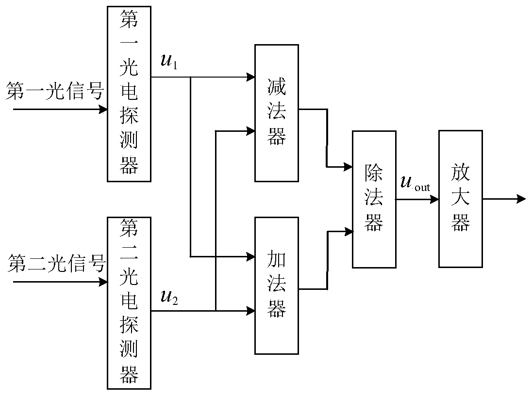
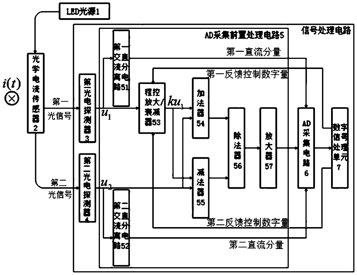
[0025] Such as figure 2 As shown, the dual-output optical current transformer provided by the present invention includes an LED light source 1, an optical current sensor 2, a first photodetector 3, a second photodetector 4, an AD acquisition preprocessing circuit 5, an AD acquisition circuit 6 and Digital signal processing unit 7.

[0026] The LED light source 1 emits light to the optical current sensor 2, the optical current sensor 2 se...


PUM


Abstract

The invention relates to a dual-output optical current transformer and a signal processing method thereof. The optical current transformer is characterized by comprising an LED (Light-Emitting Diode)light source; an optical current sensor, a first photodetector, a second photodetector, an AD (Analog-to-Digital) collection preprocessing circuit and a digital signal processing circuit, wherein theoptical current sensor is used for sensing current information of a detected conductor according to light emitted by the light source to obtain a first optical signal and a second optical signal; thefirst photodetector is used for detecting the first optical signal to obtain a first output signal; the second photodetector is used for detecting the second optical signal to obtain a second output signal; the AD collection preprocessing circuit is used for obtaining a first direct current component and a second direct current component; and the digital signal processing unit is used for converting the first direct current component information and the second direct current component information into a first feedback control digital quantity and a second feedback control digital quantity andfeeding the first feedback control digital quantity and thesecond feedback control digital quantity to the AD collection pre-processing circuit; after the AD collection pre-processing circuit obtains the output value, the digital signal processing unit demodulates the output value to obtain a current flowing through the detected conductor. The dual-output optical current transformer and the signal processing method thereof provided by the invention can be widely applied to the field of power system protection.

Description

technical field [0001] The invention relates to a dual-output optical current transformer and a signal processing method thereof, belonging to the field of power system protection. Background technique [0002] Optical current transformers measure current based on the Faraday magneto-optical effect principle, which is essentially the integration of the magnetic field along the sensing optical path. Because of its excellent performance and potential advantages, it has become the main direction of current transformer development. The optical current transformer generally obtains the measured current information by detecting the size of the Faraday rotation angle, and the signal processing methods adopted mainly include the single optical path method and the double detector subtraction method. The single optical path method eliminates the influence of light source fluctuations through the AC and DC separation method, which can effectively suppress the photoelectric common mode ...

Claims


Application Information

Patent Timeline
Patent Type & Authority Applications(China)
IPC IPC(8): G01R15/24G01R19/25
CPCG01R15/246G01R19/25
Inventor 宋璇坤于文斌肖智宏韩柳张国庆郭志忠谷松林王贵忠李洪波侯英伟冯腾刘文轩吴聪颖蔡勇
Owner STATE GRID ECONOMIC TECH RES INST CO
Why Eureka
Try Eureka