
Bionic leg type bounce experiment device

An experimental device and bionic leg technology, applied in the field of bionic machinery, can solve the problems of increasing the design cost of the control system, the inability of the single-degree-of-freedom rotary joint to adapt to the road conditions in real time, and poor motion stability

Active Publication Date: 2019-08-16
NORTHWESTERN POLYTECHNICAL UNIV
View PDF11 Cites 5 Cited by
  • Summary
  • Abstract
  • Description
  • Claims
  • Application Information

AI Technical Summary

Problems solved by technology

However, compared with the kinematic characteristics of biological leg joints, the kinematic stability of single-degree-of-freedom rotary joints is poor, and the control strategy is more complex, which requires higher requirements for data acquisition systems and data processing programs, thus improving the control system. In addition, in the face of an unstructured environment, the single-degree-of-freedom rotary joint cannot adapt to the road conditions in real time. Today, almost all experimental results show that the single-degree-of-freedom rotary joint as a bionic leg joint Footed robots can only perform relatively stable movements under a single road condition

Method used


Image

  • Bionic leg type bounce experiment device
  • Bionic leg type bounce experiment device
  • Bionic leg type bounce experiment device

Examples


Embodiment Construction

[0042] The embodiments described below by referring to the figures are exemplary and are intended to explain the present invention and should not be construed as limiting the present invention.

[0043] In describing the present invention, it should be understood that the terms "center", "longitudinal", "transverse", "length", "width", "thickness", "upper", "lower", "front", " Orientation indicated by rear, left, right, vertical, horizontal, top, bottom, inside, outside, clockwise, counterclockwise, etc. The positional relationship is based on the orientation or positional relationship shown in the drawings, which is only for the convenience of describing the present invention and simplifying the description, rather than indicating or implying that the referred device or element must have a specific orientation, be constructed and operated in a specific orientation, Therefore, it should not be construed as limiting the invention.

[0044] With reference to accompanying drawin...


PUM


Abstract

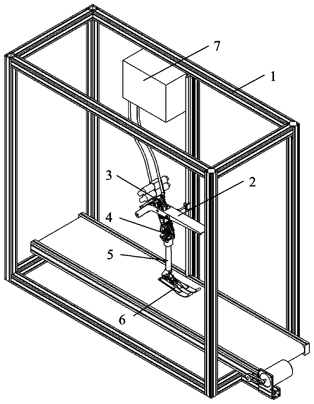
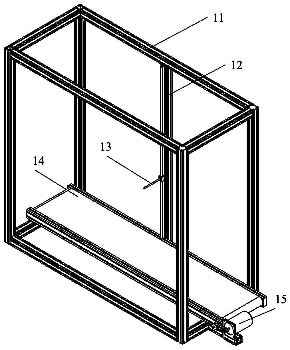
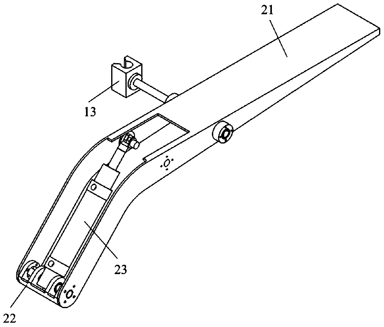
The invention discloses a bionic leg type bounce experiment device. The bionic leg type bounce experiment device comprises a frame portion, a torso portion, a thigh portion, a knee joint portion, a lower leg portion, a sole portion, and a device drive control system; and the device drive control system is used for driving and controlling the operation of the entire experimental device. According to the bionic leg type bounce experiment device, a bounce device is driven by two hydraulic cylinders, and the characteristic of a large output force of the hydraulic drive is used for improving the bearing capacity of the device; the instantaneous curvature center trajectory of a specific biological joint motion is simulated by means of the rich motion characteristics of a gear-five-bar mechanism,so that the device gait is closer to the jumping motion of the creature, and an experimental platform is provided for studying the influence of the instantaneous curvature center trajectory on the jump performance; and the method of combining the hydraulic drive and the spring drive is used as an elastic actuator of a robot, so that the hydraulic system output energy with less power can be storedand then released suddenly in a periodic manner, therefore, the required power, shape volume and weight of the hydraulic power system are reduced, and the energy utilization efficiency is improved.

Description

technical field [0001] The invention belongs to the field of bionic machinery, and in particular relates to a bionic leg-type bouncing device, in particular to a single-leg bouncing device with a hydraulic elastic driver as a power source and a bionic knee joint mechanism as a motion joint. Background technique [0002] The research on the bionic legged jumping device can provide a large amount of theoretical basis and experimental data for the research on the energy utilization efficiency, motion stability and control strategy of the bionic legged robot, and can promote the practical development of the bionic legged robot. One of the hotspots in the field. [0003] At present, the driving modes of the leg joints of the bionic leg jumping device are roughly divided into the following forms, motor drive, pneumatic drive, hydraulic drive and elastic drive drive. Among them, the elastic driver is mainly composed of a driving element and an elastic element, and the driving elem...

Claims


Application Information

Patent Timeline
Patent Type & Authority Applications(China)
IPC IPC(8): G01M13/00
CPCG01M13/00
Inventor 葛文杰刘博邹志华刘思哲
Owner NORTHWESTERN POLYTECHNICAL UNIV
Learn More