Pressure control device of fluid transportation pump

A pressure control and fluid conveying technology, applied in pump control, mechanical equipment, machine/engine, etc., can solve problems such as increasing working pressure, and achieve the effect of increasing safety, easy installation, and high working efficiency

Pending Publication Date: 2019-08-16
INTRADIN SHANGHAI MACHINERY
View PDF0 Cites 1 Cited by
  • Summary
  • Abstract
  • Description
  • Claims
  • Application Information

AI Technical Summary

Problems solved by technology

[0004] The purpose of the present invention is to provide a pressure control device for a fluid conveying pump to solve the pressure control of the pump after canceling the complicated structure of the bypass valve, to control the pressure at the front end where the high pressure is formed, and to control the complete machine without shutting down when there is high pressure. Running, energy saving and environmental protection, and the working pressure can be increased by setting the pressure value

Method used


Image

  • Pressure control device of fluid transportation pump
  • Pressure control device of fluid transportation pump
  • Pressure control device of fluid transportation pump

Examples


Embodiment Construction

[0022] In order to make the technical problems, technical solutions, and beneficial effects solved by the present invention clearer, the following further describes the present invention in detail with reference to embodiments. It should be understood that the specific embodiments described herein are only used to explain the present invention, but not to limit the present invention.

[0023] It should be understood that in the description of the present invention, the orientation or positional relationship indicated by the terms "left", "right", etc. is based on the orientation or positional relationship shown in the drawings, and is only for the convenience of describing the present invention, but not a requirement. The present invention must be constructed and operated in a specific orientation, and therefore cannot be understood as a limitation to the present invention.

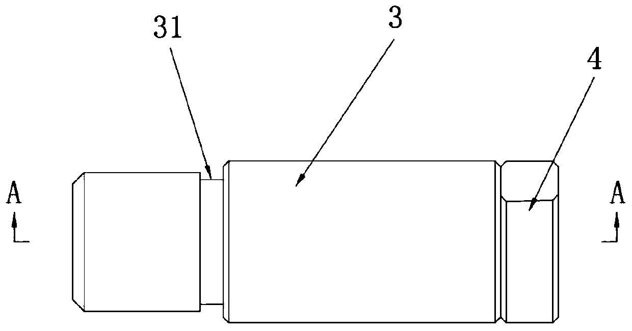
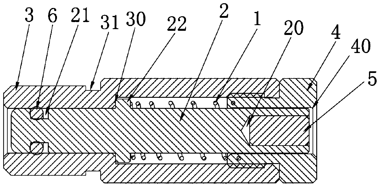
[0024] Such as Figure 1 to Figure 3 Shown and Figure 5 As shown, the present invention provides a pressur...


PUM


Abstract

The invention relates to a fluid transportation pump, in particular to a pressure control device of the fluid transportation pump. The pressure control device is arranged in a fluid medium output channel and is close to a sealing cavity formed by a pump cover and a pump body; the pressure control device is sequentially sleeved with a fixing sleeve and a pressure rod from outside to inside; the pressure rod reciprocates in the fixing sleeve; the fixing sleeve is partially embedded in a blind hole formed in the pump body; a spring for pushing the pressure rod to reset is further arranged betweenthe fixing sleeve and the pressure rod; the pressure rod is sleeved with the spring; the other end of the pressure rod is sleeved with an end cover; the end cover is connected with the fixing sleeveand is used for limiting and abutting against the spring; a through hole for reciprocating through the pressure rod is formed in the middle of the end cover; a blind hole is further formed in the tailof the pressure rod; and a magnet is arranged in the blind hole. By the aid of the pressure control device, the whole machine is controlled to shut down and stop operation under the high pressure, sothat the safety is increased, and the energy saving and environmental protection effects are achieved.

Description

Technical field [0001] The invention relates to a fluid delivery pump, in particular to a pressure control device of the fluid delivery pump. Background technique [0002] The fluid delivery pump is a commonly used positive displacement pump to transport or pressurize the fluid. It is widely used in the industrial fields of gathering and lifting. It has strong self-priming ability and high suction vacuum pressure performance, especially suitable for Unloading oil at the oil tanker terminal, and transporting oil from tank trucks, fuel trucks, oil depots and gas stations. [0003] At present, the pressure control device of the existing fluid delivery pump mostly adopts a bypass valve or a fluid internal circulation method. Among them, the structure and installation of the bypass valve control device are relatively complicated. The pump continues to run when the bypass valve is activated, which does not save energy. When the pressure is high, the fluid is discharged from the outlet c...

Claims


Application Information

Patent Timeline
Patent Type & Authority Applications(China)
IPC IPC(8): F04C14/00F04C14/06
CPCF04C14/00F04C14/06F04C2270/185
Inventor 张伟
Owner INTRADIN SHANGHAI MACHINERY
Why Eureka
Try Eureka