
Automatic parking system and method and vehicle

An automatic parking and parking technology, which is applied in the field of automatic parking systems, parking methods and vehicles with the parking system, can solve the problems of inaccurate detection of the surrounding environment of the vehicle, difficulty in opening the door, scratching accidents, etc. Achieve the effect of improving the success rate of parking, reducing vehicle scratches, and enhancing coping ability

Active Publication Date: 2019-08-16
ZHEJIANG GEELY HLDG GRP CO LTD +1
View PDF5 Cites 15 Cited by
  • Summary
  • Abstract
  • Description
  • Claims
  • Application Information

AI Technical Summary

Problems solved by technology

However, both of these detection methods have certain defects, which make the vehicle's detection of the surrounding environment inaccurate, resulting in unsatisfactory parking effects in some scenarios.
For example, in the very common underground garage scene, ultrasonic radar is very poor at identifying square pillars in the underground garage.
Ultrasonic radar cannot obtain the height information of obstacles, and it is difficult to distinguish between wall obstacles and roadsides. As a result, it is difficult to accurately control the distance between the vehicle and the wall for the parking space next to the wall. It is often too close to the wall, making it difficult to open the door, which is likely to cause scratching accidents
[0003] In addition, the existing ultrasonic and camera-integrated automatic parking solution is limited by the detection range of the side-view camera and the computing power of the image processor, so it can only simply recognize lane lines and cannot identify specific obstacles. Object type, prone to parking scratches

Method used


Image

  • Automatic parking system and method and vehicle
  • Automatic parking system and method and vehicle

Examples


Embodiment Construction

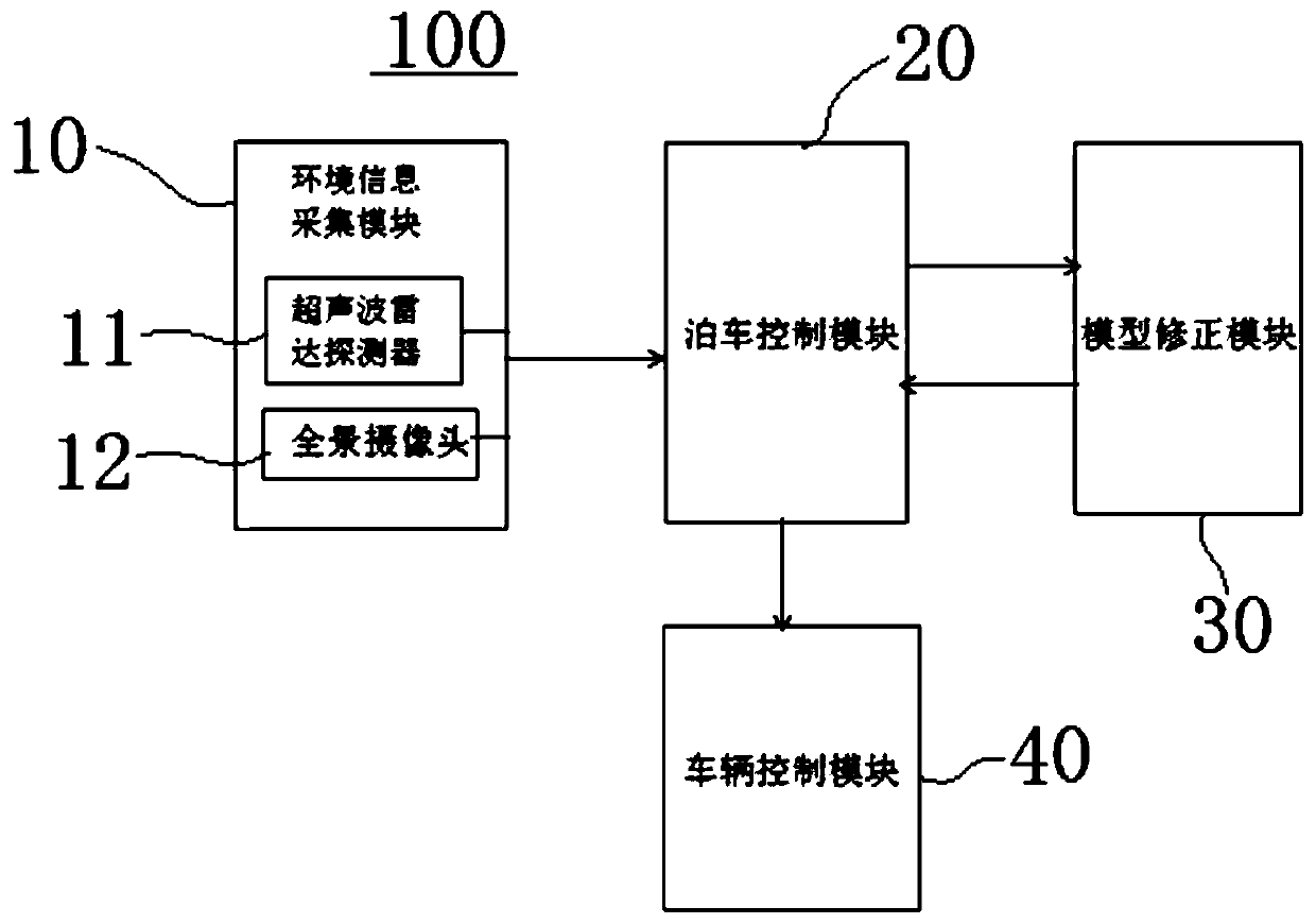
[0033] see figure 1 , the automatic parking system 100 of the embodiment of the present invention is mainly composed of an environmental information collection module 10, a parking control module 20, a model correction module 30 and a vehicle control module. Wherein, the environmental information collection module 10 is used for collecting distance data and image information between the vehicle and surrounding obstacles. The parking control module 20 is connected to the environment information collection module 10, and the environment information collection module 10 transmits the collected distance data and image information between the vehicle and surrounding obstacles to the parking control module 20 through the CAN bus.

[0034] The parking control module 20 receives the distance data and image information transmitted by the environmental information collection module 10, and the parking control module 20 establishes a parking environment model for the scene around the veh...


PUM


Abstract

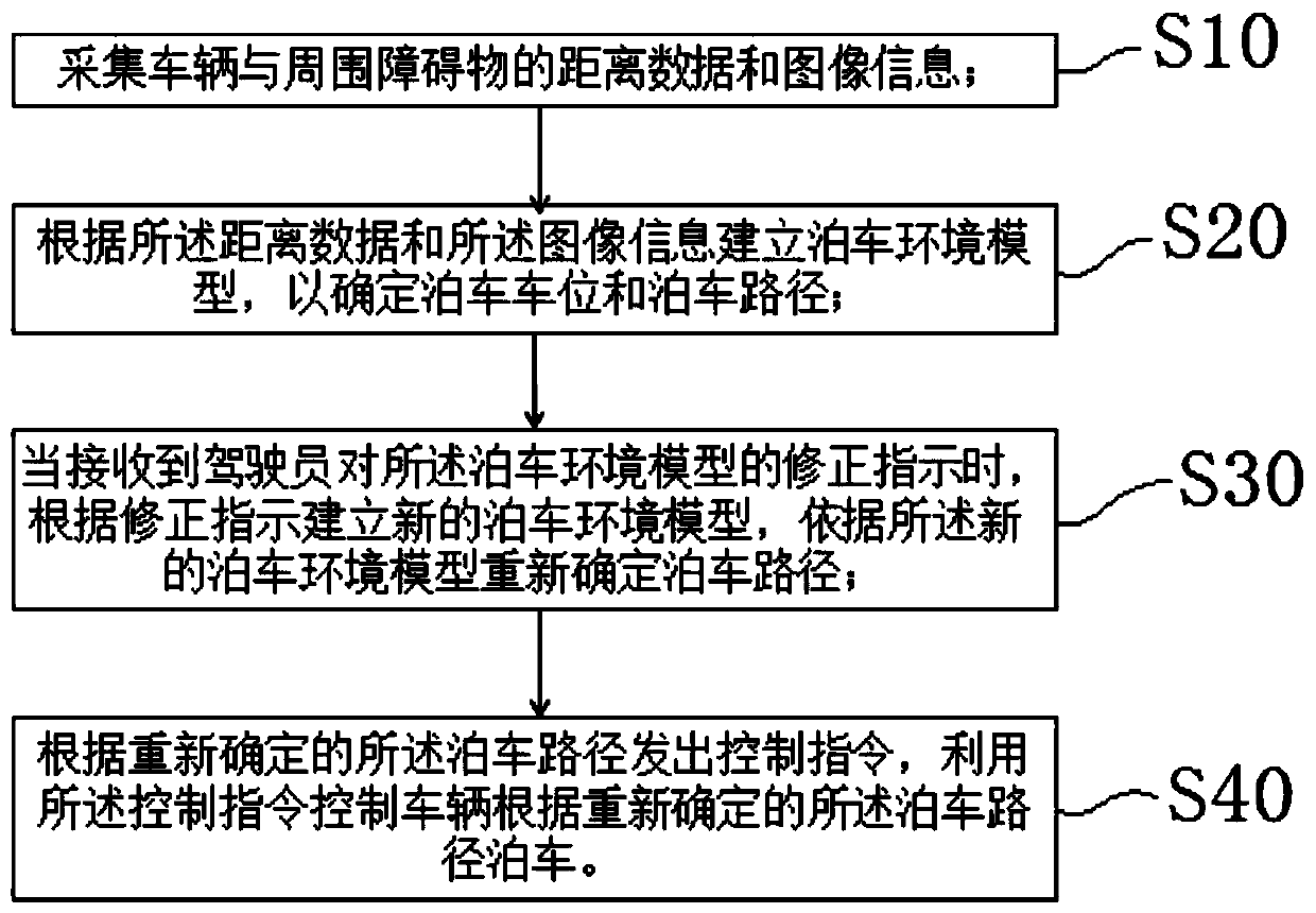
The invention provides an automatic parking system and method and a vehicle. The automatic parking system includes an environmental information acquisition module, a parking control module, a model correction module and a vehicle control module, wherein the environmental information acquisition module is used for collecting distance data and image information between the vehicle and surrounding obstacles; the parking control module is used for receiving the distance data and image information and establishing a parking environment model to determine a parking space and a parking path; the model correction module is used for receiving an correction instruction of a driver to the parking environment model to establish a new parking environment model to redefine the parking path, and the parking control module issues control instruction according to the redefined parking path; and the vehicle control module receives and executes the control instruction issued by the parking control module, and controls the vehicle to be parked according to the redefined parking path. According to the automatic parking system, the driver updates the parking environment model through the model correction module, so that the accuracy of obstacle type identification and the success rate of automatic parking are improved, and the risk of vehicle scratch is reduced.

Description

technical field [0001] The invention relates to the technical field of vehicle control, in particular to an automatic parking system, a parking method and a vehicle with the parking system. Background technique [0002] Existing automated parking systems mostly rely on ultrasonic radar or cameras around the vehicle. However, there are certain defects in these two detection methods, which make the vehicle's detection of the surrounding environment inaccurate, resulting in unsatisfactory parking effects in some scenarios. For example, in the very common underground garage scene, ultrasonic radar is very poor in identifying square pillars in the underground garage. Ultrasonic radar cannot obtain the height information of obstacles, and it is difficult to distinguish between wall obstacles and roadsides. As a result, it is difficult to accurately control the distance between the vehicle and the wall for the parking space next to the wall, which often results in being too close ...

Claims


Application Information

Patent Timeline
IPC IPC(8): B60W30/06
CPCB60W30/06
Inventor 窦子优
Owner ZHEJIANG GEELY HLDG GRP CO LTD
Learn More