Flue gas guiding system and method as well as waste heat boiler

A waste heat boiler and flue gas flow rate technology, which is applied in the field of waste heat boilers and gas turbine waste heat boilers, can solve the problems of increased heat dissipation loss of boilers, increased equipment manufacturing costs, and large impact of guide plates, so as to reduce flue gas resistance and ensure Effective utilization, uniform flow effect

Pending Publication Date: 2019-08-13
MCC CAPITAL ENGINEERING & RESEARCH
View PDF0 Cites 0 Cited by
  • Summary
  • Abstract
  • Description
  • Claims
  • Application Information

AI Technical Summary

Problems solved by technology

However, doing so will lengthen the flue and increase equipment manufacturing costs. Moreover, the lengthening of the flue duct will also increase the heat dissipation loss of the boiler and reduce the thermal efficiency of the boiler.
[0007] 2. Arrange an inflection point on the upper surface of the flue to adjust the elevation angle of the upper surface of the flue, select a suitable elevation angle, and change the upper surface of the single elevation angle to a front and rear two-stage panel with an elevation angle of 30° and 50° respectively, thereby reducing the mouth section The maximum speed of the flue gas is reduced, and the recirculation zone in the upper part of the flue is reduced, but the uniformity of the final flue gas flow has not been significantly improved
However, deflectors in this area still have shortcomings: compared with other areas, the flue gas flow velocity in the lowermost part of the flue is relatively large, and the fluctuation is relatively large. Due to the vortex impact of the flue, there is a risk of deformation and cracking of the deflector, and part of the flue gas concentrates on the bottom tube bundle; when the air velocity at the inlet of the flue is high, the deflector has to bear a greater impact
This solution cannot be directly applied to the existing operating waste heat boilers, and cannot change the harm caused by the impact of high-speed flue gas on the bottom tube bundle
[0012] These technologies can improve the uniformity of the flow field to a certain extent, but none of them can adjust the flue gas according to the flow and temperature changes of the flue gas exhausted by the gas turbine, and cannot adapt to various working conditions of the gas turbine.

Method used


Image

  • Flue gas guiding system and method as well as waste heat boiler
  • Flue gas guiding system and method as well as waste heat boiler
  • Flue gas guiding system and method as well as waste heat boiler

Examples


Embodiment Construction

[0066] The details of the present invention can be understood more clearly with reference to the accompanying drawings and the description of specific embodiments of the present invention. However, the specific embodiments of the present invention described here are only for the purpose of explaining the present invention, and should not be construed as limiting the present invention in any way. Under the teaching of the present invention, the skilled person can conceive any possible modification based on the present invention, and these should be regarded as belonging to the scope of the present invention.

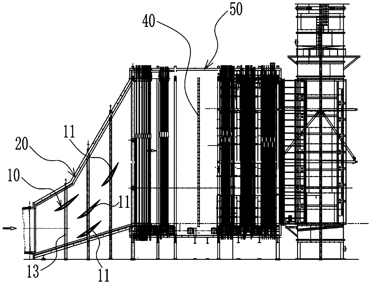
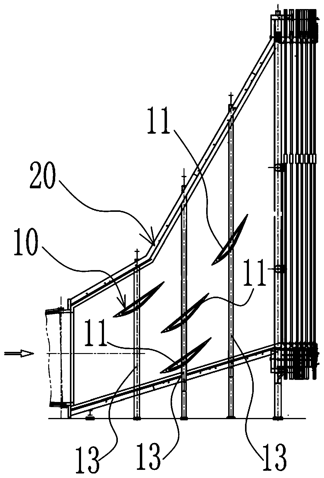
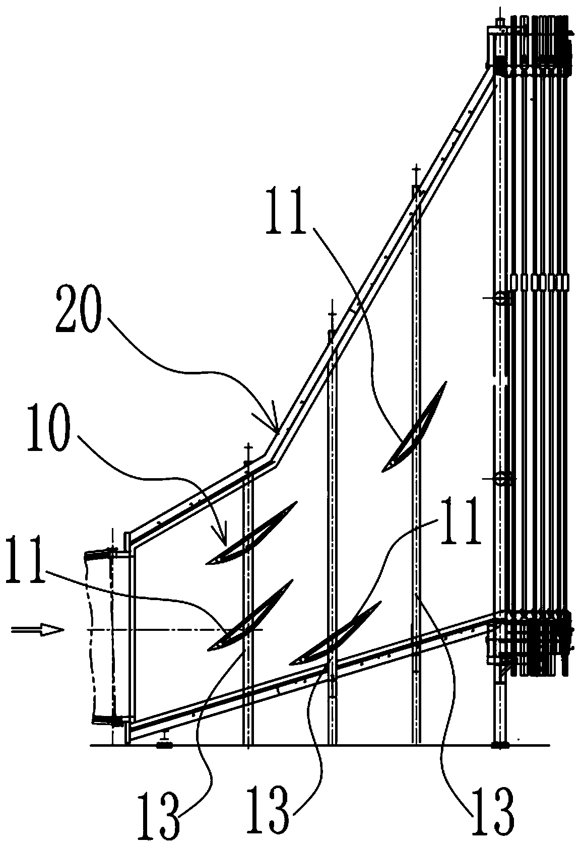
[0067] Such as Figure 1 to Figure 8 As shown, the flue gas guiding system 10 proposed by the present invention includes a plurality of guiding devices 11, a plurality of flue gas velocity detection devices and a control unit (not shown in the figure), wherein the plurality of guiding devices 11 are used for guiding waste heat For flue gas in the inlet flue 20 of the boi...


PUM


Abstract

The invention provides a flue gas guiding system and method as well as a waste heat boiler. The flue gas guiding system comprises a plurality of guiding devices, a plurality of flue gas flow velocitydetecting devices and a control unit, wherein the guiding devices are used for guiding the flow of flue gas in an inlet flue of the waste heat boiler, and comprise guiding plates and rotating mechanisms; the rotating mechanisms are capable of driving the guiding plates to rotate; the flue gas flow velocity detecting devices are used for detecting the flue gas flow velocity in different preset areas of the waste heat boiler; and the control unit is electrically connected with the rotating mechanisms and the flue gas flow velocity detecting devices, capable of receiving the value of the flue gasflow velocity, detected by the flue gas flow velocity detecting devices, in the different preset areas, and capable of adjusting or keeping the inclination angles of the corresponding guiding platesin the different preset areas by controlling the rotating mechanisms, so that the velocity distribution of the flue gas in the inlet flue of the waste heat boiler can be uniform. The flue gas guidingsystem and method as well as the waste heat boiler provided by the invention have the beneficial effects that the flue gas flow direction can be dynamically adjusted according to the flow velocity offlue gas emitted by a flue gas turbine, and then it is guaranteed that all the flue gas can uniformly enter the waste heat boiler under different working conditions.

Description

technical field [0001] The invention relates to the technical field of gas turbine waste heat boilers, in particular to a flue gas diversion system and method for waste heat boilers and other waste heat boilers with sudden expansion flue air channels, and waste heat boilers. Background technique [0002] With the increasingly serious shortage of resources and environmental pollution, energy saving and effective use of waste heat have become the common concern of the world today. The massive development and utilization of natural gas resources has led to the rapid development of high-efficiency, low-pollution gas-steam combined cycle waste heat boiler power generation technology. As one of the three major equipments of the gas-steam combined cycle, the waste heat boiler is located between the gas turbine and the steam turbine. A large number of heat exchangers are arranged to absorb the exhaust heat of the gas turbine and generate high-temperature steam for the steam generato...

Claims


Application Information

Patent Timeline
IPC IPC(8): F22B1/18F22B37/00F22B35/00
CPCF22B1/1815F22B37/00F22B35/001F22B35/007
Inventor 耿明山陈瑜
Owner MCC CAPITAL ENGINEERING & RESEARCH
Why Eureka
Try Eureka