
Automatic forming production line and automatic forming production technology for narrow-mouth circular ceramic container product

A technology for automatic molding and ceramic containers, which is applied in ceramic molding machines, ceramic molding workshops, manufacturing tools, etc. It can solve the problems of difficult grinding, laborious movement, and low degree of automation, so as to achieve easy grinding and prevent adhesion. Together, avoid the effect of chaining together

Active Publication Date: 2019-08-13
广东皓明陶瓷科技有限公司
View PDF8 Cites 1 Cited by
  • Summary
  • Abstract
  • Description
  • Claims
  • Application Information

AI Technical Summary

Problems solved by technology

[0004] There are following deficiencies in the production process of the above-mentioned narrow-mouth circular ceramic container products: 1. At the position corresponding to the interface between the left and right inner mold core blocks, the container blank will form two seams that run through the surface of the container. The positions of these two seam lines are obvious, and it is not easy to grind (because the container blank is generally rotated at high speed during grinding, but since the above seam lines run through the surface of the container from top to bottom, the entire surface of the container is ground from top to bottom. All parts need to undergo grinding); 2. The operation of separating and merging the inner and outer molds is troublesome, and the action of taking out the green body is troublesome, especially the action of horizontally splitting or horizontally merging the two inner mold core blocks, or must rely on complex mechanical equipment And action, or must rely on manual assistance of workers, the degree of automation is low; Third, in order to make the seam of the inner mold core as small as possible, the inner mold core is required to be embedded in the outer mold sleeve with a taper as tightly as possible, causing the workers to insert the inner mold When the core is taken out from the outer mold sleeve, the outer mold sleeve may be pulled upwards together with the inner mold core. It is also difficult to manually separate the core

Method used


Image

  • Automatic forming production line and automatic forming production technology for narrow-mouth circular ceramic container product
  • Automatic forming production line and automatic forming production technology for narrow-mouth circular ceramic container product
  • Automatic forming production line and automatic forming production technology for narrow-mouth circular ceramic container product

Examples


Embodiment 1

[0054] image 3 , Figure 4 , Figure 5 , Figure 6 The shown automatic molding production line for narrow-mouth circular ceramic container products includes a circulation guide rail 11 and an oven 12, the circulation guide rail 11 passes through the inner cavity of the oven 12, and a plurality of carrying trolleys 13 are installed on the circulation guide rail 11, each carrying A mold is placed on the trolley 13, and the mold is divided into a circular outer mold cover 2 and a circular inner mold core 3, and the circular inner mold core 3 is placed in the circular outer mold cover 2, and the circular outer mold cover 2 includes The peripheral wall 22 of the outer mold casing and the bottom wall 21 of the outer mold casing.

[0055] Next to the path where the mold moves along the circular guide rail, there are mud billet placement mechanism 14, rolling forming mechanism 15, and green body take-out mechanism 16 (the moving direction of the mold along the circular guide rail ...

Embodiment 2

[0062] An automatic molding production process for narrow-mouth circular ceramic container products, which adopts the automatic molding production line for narrow-mouth circular ceramic container products of Embodiment 1, and includes the following steps in sequence:

[0063] (1) The carrying trolley 13 drives the mold to move along the circular guide rail 11. The mold includes a circular outer mold sleeve 2 and a circular inner mold core 3. The circular inner mold core 3 is placed inside the circular outer mold sleeve 2. When the mold passes through When next to the mud billet placement mechanism 14, the mud billet placement mechanism 14 puts the round cake-shaped mud billet into the mould;

[0064] (2) The carrying trolley 13 continues to drive the mold to move along the circular guide rail 11. When the mold passes by the rolling forming mechanism 15, the rolling forming mechanism 15 rolls the round cake-shaped mud into a circular container with a small top and a large bottom...


PUM


Abstract

The invention relates to an automatic forming production line for a narrow-mouth circular ceramic container product. The automatic forming production line comprises a circulating guide rail and an oven; a plurality of carrying trolleys are mounted on the circulating guide rail; a mould is placed on each carrying trolley, and is divided into a circular outer mould sleeve and a circular inner mouldcore; circular annular grooves are formed in the upper parts of the circular inner mould cores; a blank taking-out mechanism comprises a horizontal hanging rail; a sliding block is mounted on the horizontal hanging rail in a horizontal sliding manner; the horizontal hanging rail is further provided with a sliding block cylinder which drives the sliding block to slide along the horizontal hanging rail; a vertical cylinder is hoisted below the sliding block; a movable bracket is hoisted at the tail end of a piston rod of the vertical cylinder; two horizontal cylinders and two arc-shaped clampingblocks are symmetrically mounted on the movable bracket; a suction disc is also mounted at the central position of the movable bracket; and an annular pressing block and a plurality of vertical springs are also mounted on the movable bracket. The invention also provides an automatic forming production technology for the narrow-mouth circular ceramic container product. The separation of inner moulds from outer moulds is simple, convenient and ingenious, and the automation degree of the production process is high.

Description

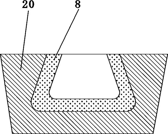
technical field [0001] The invention belongs to the technical field of ceramic production equipment, and in particular relates to an automatic molding production line and production process of narrow-mouth circular ceramic container products. Background technique [0002] The narrow-mouthed circular ceramic container has a conical shape with a small top and a large bottom, so it is impossible to directly take out the container blank 8 from the integrated mold 20 after it is formed, such as figure 1 shown. Therefore, the mold of the narrow-mouth circular ceramic container blank 8 needs to adopt the combination mode of the inner mold core and the outer mold casing. In the prior art, the inner mold core is generally composed of split left and right symmetrical inner mold core blocks 30, and is hooped by the outer mold sleeve 2, such as figure 2 shown. In this way, after the container product is formed, the inner mold core is first taken out from the outer mold casing, and t...

Claims


Application Information

Patent Timeline
IPC IPC(8): B28B15/00
CPCB28B15/00
Inventor 陈明郑秋荣曾淑蓉陈和湘李世伦陈茂林吴凯雄
Owner 广东皓明陶瓷科技有限公司
Learn More